Circuit Operation Principle The telephone remote control circuit consists of a power supply circuit, an analog off-hook circuit, a decoder/decoder circuit, and a control execution circuit, as shown in Figure 3-152.
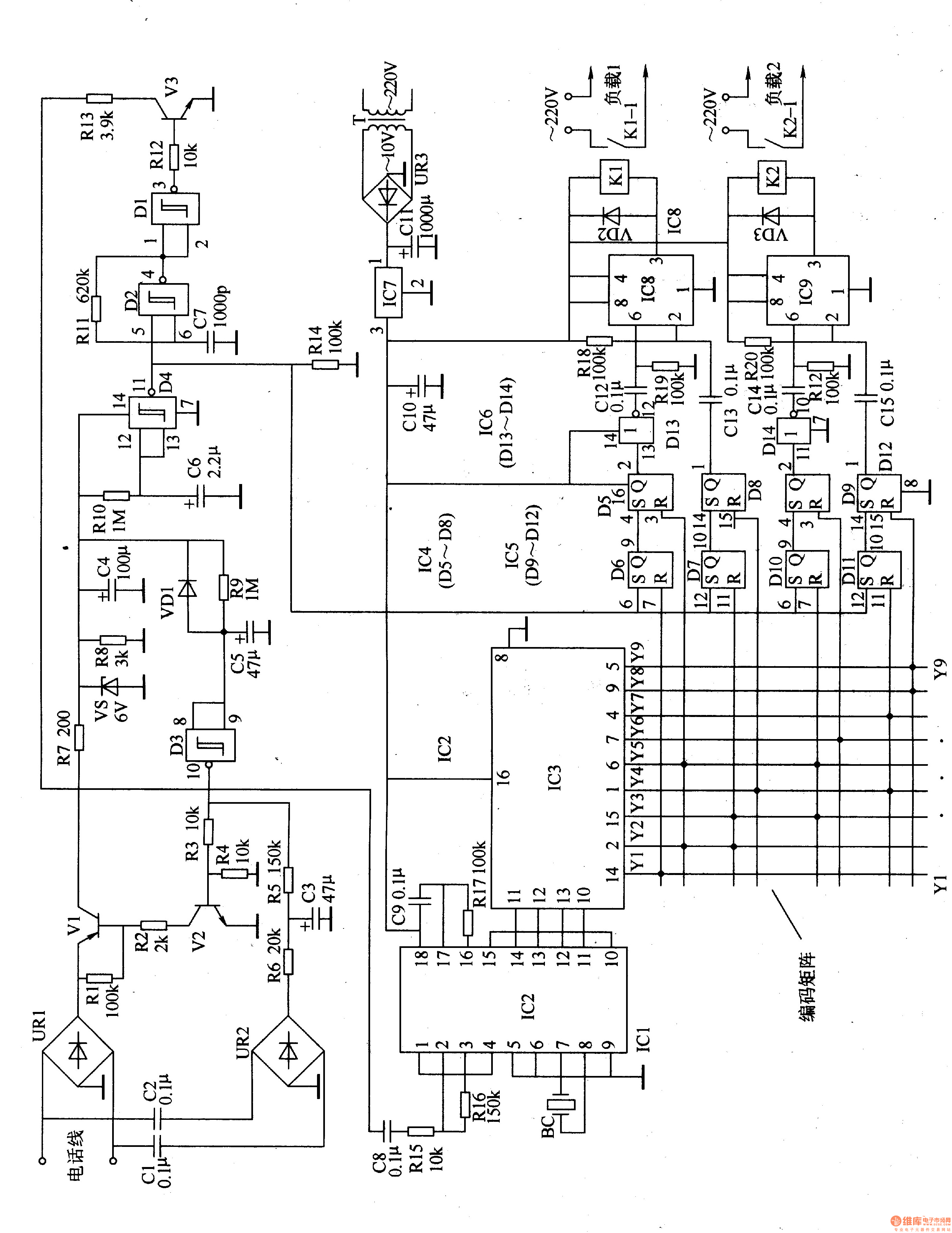
The power circuit is composed of a power transformer T, a rectifier bridge stack UR3, a filter capacitor ClO, C11, and a three-terminal voltage regulator integrated circuit IC7.
Analog electromechanical routing rectifier bridge stack URl, UR2, transistor Vl-V3, NAND gate Schmitt trigger integrated circuit ICl (Dl-D4), Zener diode VS, diode VDl, resistor Rl-R14 and capacitor Cl- C7 composition.
The decoder/decoder circuit is composed of a decoding integrated circuit IC2, a decoder integrated circuit IC3, a quartz crystal oscillator BC, resistors R15-R17, and capacitors C8, C9.
The control execution circuit consists of RS flip-flop integrated circuits IC4 (D5-D8), IC5 (D9-Dl2), non-gate integrated circuit IC6 (D13, D14), time base integrated circuit IC8, 1C9, relay Kl, K2, diode VD2. VD3, resistor R18-R2l and capacitor Cl2-Cl5.
The AC 220V voltage is supplied with +6V DC voltage for IC2-IC9 after T step-down, UR3 rectification, Cll filtering and IC7 regulation.
The Yl-Yg output of IC3 is connected to the coding matrix circuit. By changing the connection point of the coding matrix, the passwords of the two power supply "on" and "off" can be set. In this circuit, the power supply "on" password for the first load is "15", the "off" password for the power supply is "24", and the second drive power supply "on" password is "36". The power "off" password is "49".
When using, dial the phone in the home. When the ringing tone is 3 times, you can hear the tone of 35. Enter the two-digit "on" or "off" password within 60s after the end of the tone. Remote control of household appliances. After 60s, the telephone and telephone remote control automatically hang up.
When dialing the home phone, the AC ringing signal is rectified by UR1, UR2 and R6 and C3, so that Vl and V2 are turned on to realize the off-hook. The DC voltage output from the Vl collector is limited by R7 and VS regulated, which provides +6V working voltage for ICl (the voltage disappears after 60s).
Since the voltage across C6 cannot be abrupt, when the voltage of +6V is just established at both ends of VS, D4 outputs a high level, so that the prompt sound circuit (composed of Dl, D2, V3 and Rll-R13, C7) works, and the frequency is 1.5. kHz audio alert signal. After about 3 seconds, C6 is charged and D4 is output low, and the tone circuit stops working.
When the user inputs a two-digit password through the telephone, a double-tone encoding (DTMF) control signal is issued, and the DTMF signal is processed by UR1, Vl, C8, and Rl5, and is enlarged from the 2 pin (input) of IC2. IC2 decodes the input DTMF signal into a 4-bit binary code (BCD code), and then sends the IC3 to a decimal code. The decimal code signal controls the working states of lC8, 1Cg, and Kl, K2 through the RS flip-flop integrated circuit IC4, 1C5 and the non-gate integrated circuit IC6. When the user inputs the "15" password, the Y1 end (14 feet) of IC3 and YS The terminal (6-pin) outputs a high level, so that the 3 pin of IC8 outputs a low level, the relay K1 pulls in, and its normally open contact turns on the working power of the load 1.
When the user inputs the "24" password, the YZ terminal (2 feet) and the Y4 terminal (1 pin) of IC3 output a high level, and the 3 pin of IC8 becomes a high level, so that Kl is released, and its normally open contact will load. The working power of 1 is disconnected.
When the user inputs the "36" password, the Y3 end (15 feet) and the Y6 end (7 feet) of IC3 output a high level, so that the 3 pin of IC9 outputs a low level, K2 pulls in, and its normally open contact will load. The working power of 2 is turned on.
When the user inputs the "49" password, the Y4 terminal (1 pin) and the Yg terminal (5 pin) of IC3 output a high level, so that the 3 pin of IC9 becomes a high level, KZ is released, and its normally open contact will load 2 working power is disconnected.
Component selection
Rl-R2l uses 1/4W carbon film resistor or metal film resistor.
Cl, C2, C8, C9 and Cl2-Cl5 are all selected from monolithic capacitors or polyester capacitors with a withstand voltage of 63V; C3-C6, ClO and Cll are all selected from aluminum electrolytic capacitors with a withstand voltage of 16V; C7 uses high-frequency ceramics. Capacitor.
VDl-VD3 selects 1N4001 or 1N4007 silicon rectifier diodes.
VS selects 1/2W, 6V silicon regulator diode.
URl and UR2 use 0.1-0.5A, 2OOV rectifier bridge stack; UR3 selects 1A, 5OV rectifier bridge stack.
Vl selects 3CGl70 or 2SA605 type silicon PNP transistor; V2 selects 3DGl80K or 2SC507 type silicon NPN transistor; V3 selects S9014 or 3DG9014 type silicon NPN transistor.
lCl selects CD4093 type four NAND gate Schmitt trigger integrated circuit; IC2 selects MT8870 or CM8870 type dual tone multi-frequency decoding integrated circuit; IC3 selects CD4028 type BCD code-decimal decoder integrated circuit; IC4 and 1C5 select CD4043 type RS flip-flop integrated circuit; IC6 selects CD4069 type six-gate integrated circuit; IC7 selects LM7806 type three-terminal regulator integrated circuit; IC8 and 1C9 select NE555 type time base integrated circuit.
Kl and Ba are both selected 6V DC relays, their working current should be less than 200mA, the contact current capacity should be based on the power of the load.
T selects 3W, the secondary voltage is lOV power transformer.
BC uses a 3.579MHz quartz crystal oscillator.
ZGAR Aurora 1800 Puffs
ZGAR electronic cigarette uses high-tech R&D, food grade disposable pod device and high-quality raw material. All package designs are Original IP. Our designer team is from Hong Kong. We have very high requirements for product quality, flavors taste and packaging design. The E-liquid is imported, materials are food grade, and assembly plant is medical-grade dust-free workshops.
Our products include disposable e-cigarettes, rechargeable e-cigarettes, rechargreable disposable vape pen, and various of flavors of cigarette cartridges. From 600puffs to 5000puffs, ZGAR bar Disposable offer high-tech R&D, E-cigarette improves battery capacity, We offer various of flavors and support customization. And printing designs can be customized. We have our own professional team and competitive quotations for any OEM or ODM works.
We supply OEM rechargeable disposable vape pen,OEM disposable electronic cigarette,ODM disposable vape pen,ODM disposable electronic cigarette,OEM/ODM vape pen e-cigarette,OEM/ODM atomizer device.

Aurora 1800 Puffs,ZGAR Aurora 1800 Puffs Pod System Vape,ZGAR Aurora 1800 Puffs Pos Systems Touch Screen,ZGAR Aurora 1800 Puffs Disposable Vape Pod System,1800Puffs Pod Vape System
Zgar International (M) SDN BHD , https://www.zgarvapepen.com