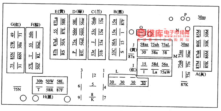
The bottom of the central junction box is the connector collection that leads to the various harnesses of the entire car. Among them, there are 6 harnesses from the instrument panel and the front wall, 2 harnesses from the left front of the car, 1 harness from the right front, 1 harness from the rear, and some double-head or single-head connectors. Their locations are shown in Figure 1. Knowing the connector position and wire code can be very helpful for reading later.

Seen from the figure:
A plug: gray, 8 lines, belonging to the dashboard wiring harness, wherein the wire codes on the wiring diagram are A87M, A87aK, A86K, A85M, A85K, A86M, A3OK, A3OM.
B plug: black, 8 lines, belonging to the right front harness, the code of each wire is: B53C, B5OA, Bl5a, Bl5a, BS, Bl5, BI, B87F.
C plug: blue, 8 wires, for the dashboard harness. Wire numbers are C53e, CJ, C53C, C56aK, C3Ib, Cl5a, Cl5a, Cl5a.
D plug: green, 8 lines, the front left harness, wire code is DP, D75a, D56br, D58L, D85L, D56aL, D56ar.
E plug: yellow, 8 lines, the front left harness, wire code is E87h, E87aL, E55, E87La, ERS, E5OA, E87L, E58R.
F plug: brown, 7 lines, for the instrument panel line, the wire code is F57L, FT, F55, F56b, F5OZ, FRL, F3OaL.
G plug: red, 8 lines, for the wiring harness of the instrument panel, the wire code is G75, G85N, G57R, G4g, G3l, G86N, G3Oa, G71.
H plug: black, 6 lines, for the rear wiring harness, the wire code is H3Ob, H5OW, H58L, HT, H58R, H87F.
I plug: red, 6 lines, the wiring harness of the instrument panel, the wire code is: 115, 158d, 156a, II, ILa, 175aw.
J plug: yellow, 6 lines, is the wiring harness of the instrument panel, the wire code is J58as, J75ah, J75aL, J3O, J58a, J58.
Also, connectors such as L, M, N, O, P, 87a, 75N, and 3Oas are single-wire or two-wire connectors.
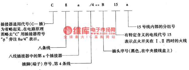
It can be seen from the above wire code and wiring diagram that the same wire in the connector that the wire card intersects with the central junction box often has two codes in the original vehicle data, one of which indicates that the wire is plugged in several lines. A certain position in the device, another code indicates that the wire is in a certain connector of the central junction box (represented by the letters A, B, C...) a circuit (such as 300, 15, 15, 58... ...), this line representation can help with line assembly.
Two different line codes are as follows: 
In the schematic, we use letters to indicate the following grounding locations:
A point instrument panel with iron trunk line;
B point clamps the left side of the column;
C point connection bracket grounding, in the left front harness of the car;
Point D is located near the left rear lamp holder;
E point instrument panel switch wiring behind;
F point clamps the left side of the column;
G point on the helium manifold;
O point battery negative.
The end of the iron is placed on the metal shell of the component and the body is grounded. The ground wire is connected by a brown or brown colored light with a different color stripe.
Three Phase Voltage Stabilizer
PC PC-SVC Three Phase series Voltage Stabilizer has the low energy consumption,the over voltage protection,the low voltage protection,the over-current protection,the over-loading protection,the over-temperature protection and so on.It boasts for many kinds of protections,the collection energy conservation and the environmental protection ect.This is a brand-new concept product which possess many new technologies!This series products simultaneously ha applied for many technical monopolies
We already applied many kinds of this products patent, and the technical patent NO: 200720036394.1 and Appearance paten NO: 200730025909.3
2. Use for equipment:
Computer
Test equipment
Light system
Safe alarm system
Ray equipment
Medical equipment
Copy machine
Stereo equipment
Numerical control machine tools
Industrial automation equipment
Color and drying equipment
Test equipment
Three Phase Voltage Stabilizer,3 Phase Stabilizer,3 Phase Voltage Stabilizer,Three Phase Stabilizer
zhejiang ttn electric co.,ltd , https://www.ttnpower.com