(2) Nanjing Iveco
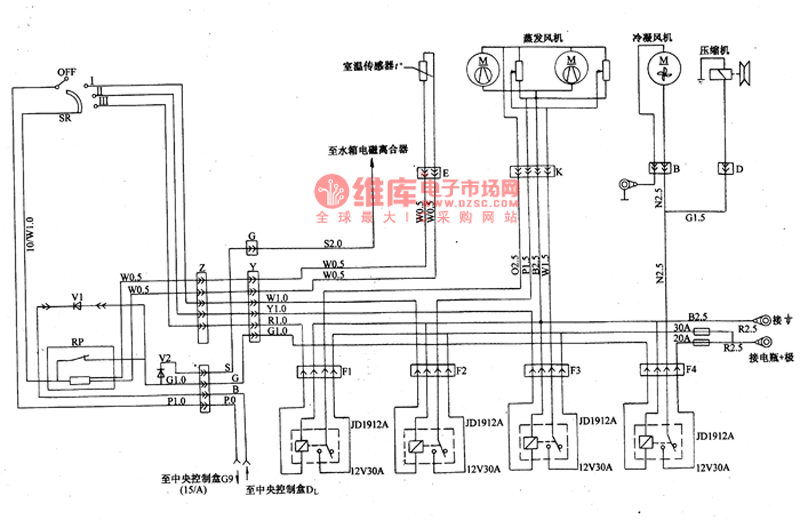
35.10 Light-duty vehicle Zhongnan Company produces air-conditioning circuit diagram (Figure 22).
The live wire of the air volume switch SR comes from the G9 terminal of the car ignition switch 15/A column control (in the central junction box), and the live wire of the relays F1, F2, F3, F4 is connected to the positive battery (red line, 2.5
(mm) 3), one end of the control coil is connected to a 2.5 (mm) 2 ground wire. When F1 is sucked, the evaporator fan is rapidly cooled; when F2 is sucked, the low-speed cooling F3 picks up the medium-speed cooling, and when the F4 picks up, the condenser fan and the compressor work at the same time.
The SR switch works as follows:
I block: Turn on the F2 relay, the current should reach the two evaporator fans through the overall speed reduction resistor, and cool (or ventilate) at low speed.
II block: Turn on the F3 relay, the current reaches the two evaporator fans through the speed reduction resistor, and the medium speed cooling (or ventilation).
III gear: Turn on the F1 relay, the current from the 30A fuse is directly connected to the evaporator fan, high-speed cooling (or ventilation).
The temperature control switch RP automatically closes above the set temperature value, so that the electromagnetic clutch is closed, the condenser fan is connected to the compressor, and if the switch is turned on, the switch SR only controls the ventilation air volume.

MTP And MPO Cable Assembly,Optical Patch Cable,Fibre Optic Cable Assembly,Optical Jumper
Huizhou Fibercan Industrial Co.Ltd , https://www.fibercan-network.com