Organic light-emitting diode display (OLED) is an emerging technology that will revolutionize the display industry. Organic materials used in OLED emit light when current flows, and OLED has many advantages compared to current LCD technology. One of the advantages is that it is easy to manufacture, and ultimately a lower cost display can be formed. Performance advantages include faster response time, wider viewing angles, lower power consumption, and brighter / higher contrast images. The core advantage is that OLED uses a self-luminous technology, so no backlight is needed. This not only saves power consumption, but also enables displays with a thickness of only 1mm.
Similar to LCD displays, OLED displays are available in passive matrix and active matrix configurations. When a passive matrix is ​​used, the display is connected as a grid of diodes, and each diode constitutes an independent OLED pixel. An external drive circuit can be used to light up one row of grids at a time. In contrast, active matrix displays contain transistors and pixels can be lit continuously. However, the difference between OLED and LCD is that OLED adopts a current-driven matrix mode, which will increase the complexity of active matrix design. Therefore, passive matrix products (PMOLED) are still used in large quantities of OLEDs. These PMOLEDs can be used in a variety of devices, including cellular phones, car stereos, MP3 players, and other consumer products.
OLED display power supply
Because many OLED displays are currently used in portable applications, power consumption is particularly important. Any power chip must work at the highest efficiency to save power as much as possible and extend battery life, especially when the display is not working.
The power requirements of OLED displays are related to many factors. Since the display is current-driven, the peak current requirement depends on the total number of pixels that are lit at the same time and the maximum current value that drives them. The display driver circuit also consumes some current. The voltage requirement depends on the forward voltage drop of the diode, the voltage drop of the interconnects (often showing resistance) in the display, and all the voltage drops required by the display driver (see Figure 1).
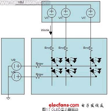
In this example, the maximum voltage required is given by the following formula:
![]()
Among them: V diode is the forward voltage drop of the diode; I diode is the current flowing through the diode; Rcol is the resistance of the column connection; Rrow is the resistance of the row metal; VCD is the overhead required by the column driver; VRD is required by the row driver The overhead; in a typical application, VIN is about 20V.
The peak current is equal to:
![]()
Among them: I diode is the current flowing through the diode; X pixels are the number of pixels that light up at a time; ICD is the current supplied to the column driver; IRD is the current supplied to the row driver.
Portable display energy saving
For a portable device with an LCD display, if it does not work for a period of time, it is common practice to turn off the backlight and turn off the display completely after a few seconds. The OLED display does not have a backlight, so the screen usually dims after a period of inactivity, and then power off after a period of time. As can be seen from Equation 1, if the current of the display is reduced, the maximum voltage required will also be reduced. In a typical application where the supply voltage is constant, this extra voltage will drop on the column driver, resulting in additional power consumption and waste of energy. By reducing the supply voltage, this energy is no longer consumed on the column driver, and the system efficiency is improved.
OLED power chip
There are already new devices on the market that specifically power PMOLED displays in portable devices. An ideal power supply device suitable for this type of application should have a very efficient boost converter that can operate on battery voltage in portable applications or on pre-rectified power in the device. Functions such as output load disconnection and low standby current are very important to reduce battery leakage when the display is not illuminated. The ideal device also requires fewer external components and a smaller package size to minimize the physical dimensions of current compact handheld devices.
Boost converter
The boost converter used should be able to work in the 2.4V to 5.5V voltage range. This range covers the entire input range of the lithium-ion battery, and should also be able to work under pre-rectified 3V or 5V rails. The output voltage range required for this type of application is 12 to 25V. The optimized power chip design will also integrate boost FETs and Schottky diodes, thereby reducing the need for external components. 1.2A FETs generally support output voltages up to 28V, with efficiencies up to 90%.
Automotive Connectors,Automotive Connector,Cable Wire Connectors,Cable Wire Connector
YUEQING WEIMAI ELECTRONICS CO.,LTD , https://www.weimaicarconn.com