With the rapid development of the transportation industry, the phenomenon of vehicle overload is also becoming more and more serious. This will not only destroy road facilities, but also increase the incidence of traffic accidents, which will cause great harm to people's lives and property. It is important to discover and manage overloaded vehicles in a timely manner.
This article refers to the address: http://
The technologies commonly used to detect overweight vehicles are: static weighing technology and dynamic weighing technology, both of which are used to set the level at specific locations on the road, to install the floor scale using pressure sensors, resistance strain sensors, etc. To detect whether the vehicle is overweight and the measurement results are accurate, but the two technologies have some common shortcomings: the sensor is easily damaged, and there are many places that cannot be supervised when setting the level at a specific location.
Based on the above considerations, this paper proposes a vehicle overweight monitoring and alarming system, which uses ultrasonic sensors to measure the relative displacement of the vehicle beam and axle when the vehicle is loaded, and indirectly measures whether the vehicle is overweight by sensor calibration. Once the vehicle is overweight, the system The GPS module locates the vehicle and transmits the overweight information and the positioning information to the monitoring center through the GSM network, and the monitoring center analyzes, records and saves the information. In this way, the sensor is not only not easily damaged, but also realizes the vehicle, and realizes remote real-time monitoring of the overloaded vehicle.
1 system composition and working principle
The system mainly includes two parts: the vehicle detection subsystem and the monitoring center. The system block diagram is shown as 1.
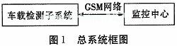
The main working principle is: during the running of the vehicle, the on-board detection subsystem detects whether the vehicle is overweight. If the vehicle is overweight, it generates alarm information, and sends the alarm information to the monitoring center through the GSM module. After the monitoring center analyzes and processes the information, it will Important data records are saved and processed for overloaded vehicles.
2 Vehicle detection subsystem
2.1 Hardware composition
The structure of the vehicle detection subsystem is shown in Figure 2, which includes two parts: the weight measurement module and the main control unit. The weighing module comprises four parts: a single chip microcomputer, an ultrasonic sensor, a temperature sensor and a wireless transmission module; the main control unit comprises a single chip, a GPS module, a GSM module and a wireless transmission module. In addition, the system uses three weight measuring modules, which are triangularly distributed in three positions of the axle. The purpose of this is to prevent uneven distribution of vehicle load and local weight, resulting in false alarms.
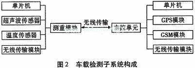
The working principle is: during the driving process, the three weighing modules respectively use ultrasonic sensors to detect the relative displacement of the axle and the beam at the position where the vehicle is loaded. After digital filtering and temperature compensation, the data will be obtained. The wireless transmission module sends the data to the main control unit, and the main control unit integrates the data to obtain the weight of the vehicle, and then compares it with the rated load of the vehicle to determine whether the vehicle is overweight. If the vehicle is overweight, the main control unit generates an alarm message, and the license plate number, rated load, overweight data and GPS positioning information of the vehicle are sent to the monitoring center through the GSM module.
2.2 Ultrasonic ranging principle
The ultrasonic ranging method used in this system is ultrasonic pulse reflection method. The principle is that the ultrasonic transmitter emits a single or a group of ultrasonic pulses, and the timer starts to count at the time of transmission, and the ultrasonic wave propagates in the air, encountering the target under test. After the reflection reaches the ultrasonic receiving end, the timer stops counting, and the obtained time t is the time when the ultrasonic wave propagates back and forth between the transmitter and the measured object.
The formula for ranging is expressed as:
s=C·△t/2 (1)
Where s is the measured distance; C is the propagation speed of the ultrasonic wave in the air; Δt is the difference between the ultrasonic transmission and reception time.
According to the above ultrasonic ranging formula, it is known that the error of the ranging is caused by the propagation velocity error of the ultrasonic wave and the time error of the measurement distance propagation. The time error can be reduced by the precise timing of the microcontroller. The speed error is related to the air density, and the air density is related to the temperature. The temperature sensor can measure the current temperature for temperature compensation. The relationship between the propagation velocity C of ultrasonic waves in the air and the ambient temperature is as shown in equation (2):
C=331.4+0.61×T (2)
The temperature compensation method is to calculate the current sound velocity C according to the equation (2) each time, and then calculate the distance s according to the equation (1).
2.3 GPS positioning principle
Since the position of the satellite is accurate, we can get the distance from the satellite to the receiver in the GPS observation. Using the distance formula in the three-dimensional coordinates, in the GPS positioning, three satellites can list three position equations and solve the problem. The position of the observation point (X, Y, Z). Taking into account the error between the satellite's clock and the receiver's clock, the fourth unknown, the clock difference, is added, so the fourth satellite is introduced, and the fourth equation is listed. By solving this equation, we get the observation. The latitude and longitude and elevation of the point. In fact, the receiver can often lock more than 4 satellites. In this case, the receiver can be divided into groups according to the constellation distribution of the satellite, each group of 4, and then the algorithm selects the group with the smallest error for positioning. Improve positioning accuracy.
2.4 Use of the GSM module
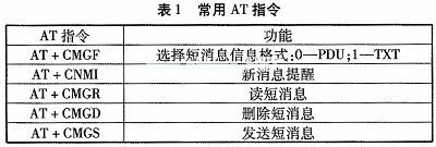
The GSM short message module is a module specially used for receiving and transmitting short messages. It has an RS-232 communication port and can be directly connected to a single chip microcomputer or a computer. The MCU and the computer send an AT command to the GSM module through the RS232 serial port to control the GSM module to send and receive text messages, set the SMS center number, SMS format, and the like. Commonly used AT commands are shown in Table 1:
2.5 Specific implementation of each functional module
1) The main control unit and the single-chip of the weighing module all use STC89C52, which has low power consumption, high performance and low price, and is used in this system without waste of resources.
2) Ultrasonic sensor is selected from KS101B produced by Qingxin Electromechanical Industry Co., Ltd. The detection range of the sensor is 1 cm ~ 550 cm, the detection frequency can reach 500 Hz, support multi-range detection, 1 ms fast light intensity detection, accuracy up to 1 mm , blind zone 1 cm.
3) The temperature sensor uses the digital temperature sensor DS18B20 manufactured by Dallas Semiconductor Co., USA to complete the temperature compensation for ultrasonic detection.
4) The wireless transmission module uses a single-chip wireless transceiver chip NRF24L01 manufactured by NORDIC and operates in the ISM band of 2.4 GHz to 2.5 GHz. The chip has a 4-wire SPI communication port and a communication rate of up to 8 Mbps. MCU connection, simple programming.
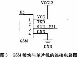
5) The SIM300 is selected for the GSM module. The hardware interface between GSM and MCU uses the RS232 communication standard. The GSM RXD is connected to the TXD and GND of the single-chip microcomputer and connected to the GND to communicate with the single-chip microcomputer. The single-chip microcomputer realizes the control of GSM by sending the AT command. The specific implementation circuit between them is shown in Figure 3.
Ac Contactor,Contactor For Ac Unit,Compressor Contactor,Air Conditioner Contactor
NanJing QUANNING electric Co.,Ltd , https://www.quanningtrading.com