Buck-up and battery charger with built-in MPPT solar system for efficiency and cost
Solar energy is green energy and it's free, but it can often be less reliable. Temperature changes can cause the best power of the solar panel to provide a point offset. In addition, equipment aging, localized illumination can be blocked, sunsets, contamination by animal waste, etc., can hinder the performance of solar panels. Based on these reliability and variability issues, almost all solar-powered devices use rechargeable batteries to provide backup power; in the past, only lead-acid batteries were used, and the types of batteries used now have expanded to include lithium batteries.
Solar-powered applications are equipped with a recharging system to capture as much solar energy as possible to quickly charge the battery and maintain the state of charge of the battery. In addition, the amount of battery leakage is critical when the solar panel receives little or no illumination, and should be minimized whenever possible.
Clearly, solar-powered applications are in the midst of growth. There are now a variety of different sizes of solar panels that can power a variety of innovative applications, such as crosswalk signage, garbage compactors, marine buoys, etc.; some solar powered applications use deep cycle batteries, Withstanding many repetitive charging cycles and deep discharges, such batteries are commonly found in "off-grid" (ie, disconnected from power company grids) renewable energy systems, such as solar or wind power systems. In the case of off-grid systems, system uptime is very important because such systems are not easily accessible.
Solar panel basics
In terms of a certain amount of light energy and operating conditions, a solar panel produces a peak output power at a particular output voltage. Figure 1 shows the characteristics of a solar panel consisting of seventy-two cells at a panel temperature of 60 °C. The dashed line represents the IV curve of the panel and the X-axis represents the panel voltage. The solid line indicates the output power produced by the panel when the panel voltage changes from 0V to the open circuit voltage of the panel; the battery voltage change is achieved with a simple load box.
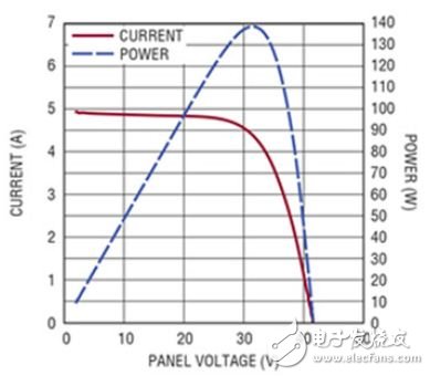
Figure 1 shows a simple power curve for a solar panel in the absence of local illumination being occluded.
For the specific case described here, the maximum power point is 32V and the panel provides 140W of power. If the panel temperature variation is allowed, this is of course allowed in the real world, then the maximum power point may vary between 28V on hot days and 44V in cold winters.
Many simpler solar charging systems set the panel voltage operating point to a fixed value; in the case of the specific panel described above, such a simpler system would set the panel operating point to 32V at a given temperature. The maximum power is taken, and the temperature of this example is 60 °C. However, when the panel temperature changes, a lot of power is wasted because the panel does not work at the true maximum power point. In such cases, more than 20-30% of the available power may be wasted.
To make matters worse, according to the implemented safety standards, most panels must be equipped with bypass diodes in the solar array; the reason for this is that some of the panels are covered and the sun is not available. When the light is shining and the other parts are exposed to sufficient sunlight, the solar panel will have some special conditions.
At this time, the hidden solar cell is reverse biased, but there is still a large current flowing through it, because other batteries that are sufficiently illuminated are supplying current, and the temperature of the blocked battery may rise, which may Causes a fire. To help reduce the risk of fire, manufacturers have placed bypass diodes throughout the panel. Figure 2 shows how the bypass diode is placed on the solar panel of the 72-cell battery.
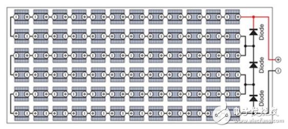
Figure 2 For safety reasons, three bypass diodes are placed on the solar panel of the seventy-two battery.
Due to the presence of bypass diodes in the panel, complex power-voltage characteristics can occur when some of the panels are blocked. Figure 3 shows this situation where two local maximum power points occur, one at 21V and the other at 37V. If the simple 32V power point setting method described above is used, then 79.4W of power can be obtained instead of 90.1W available at the true maximum power point of 21V; this indicates that 13.5% of the power is lost in this case. Obviously, systems that track the true maximum power point and work on it will have excellent power performance.
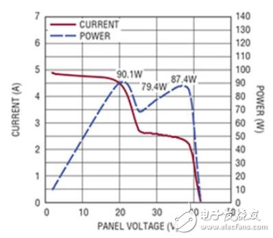
Figure 3 When the solar panel is partially occluded, a more complex power curve is produced.
Lcd Integrated Display,Lcd Panel Indoor Display,Good Angle Lcd Segment Display,Va Lcd Panel Display
Wuxi Ark Technology Electronic Co.,Ltd. , https://www.arkledcn.com