Optical coupler (optical coupler) is also called photoelectric isolator, photocoupler or photocoupler. It is a device that uses light as a medium to transmit electrical signals. Usually, the light emitter (infrared light emitting diode LED) and the light receiver (photosensitive semiconductor tube) are packaged in the same package. When the input terminal is energized, the light-emitting diode emits light, and the phototransistor generates light current after receiving the light, which flows out from the output end, thereby realizing the "electricity-light-electricity" conversion. The typical application circuit is shown in Figure 1-1 below.
The main advantages of the optocoupler are: one-way signal transmission, the input terminal and the output terminal fully realize the complete electrical isolation of the front end and the load, the output signal has no effect on the input terminal, reduce circuit interference, simplify circuit design, stable operation, no touch Point, long service life and high transmission efficiency. Optocouplers are new devices developed in the 1970s, and are now widely used in electrical insulation, level conversion, inter-stage coupling, drive circuits, switching circuits, choppers, multivibrators, signal isolation, inter-stage isolation Pulse amplifier circuit, digital instrument, long-distance signal transmission, pulse amplifier, solid state relay (SSR), instrumentation, communication equipment and microcomputer interface. In a monolithic switching power supply, a linear optocoupler can be used to form an optocoupler feedback circuit, and the duty cycle can be changed by adjusting the control terminal current to achieve the purpose of precision voltage regulation.
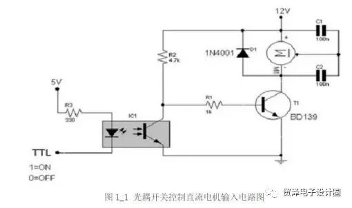
Typical circuit of optocoupler
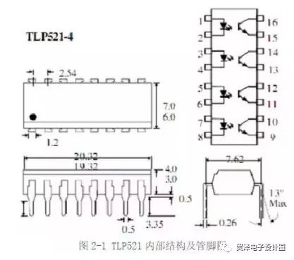
The optocoupler models commonly used for feedback include TLP521 and PC817. Here takes TLP521 as an example to introduce the characteristics of this type of optocoupler. Figure 2-1 shows the internal structure and pin diagram of the optocoupler.
The primary side of the TLP521 is equivalent to a light-emitting diode. The larger the primary side current If, the stronger the light intensity, and the greater the secondary side transistor current Ic. The ratio of the secondary transistor current Ic to the primary diode current If is called the current amplification factor of the optocoupler, and this factor changes with temperature and is greatly affected by temperature. The optocoupler used for feedback is to use the "primary current change will cause the secondary current change" to realize the feedback. Therefore, in the occasion where the ambient temperature changes drastically, due to the large temperature drift of the amplification factor, it should not be implemented by the optocoupler Feedback. In addition, the use of this type of optocoupler must pay attention to the design of peripheral parameters to make it work in a relatively wide linear band, otherwise the circuit is too sensitive to operating parameters, which is not conducive to the stable operation of the circuit.
Usually choose TL431 combined with TLP521 for feedback. At this time, the working principle of TL431 is equivalent to a voltage error amplifier with an internal reference of 2.5 V (the output voltage is error-amplified and compared, and then the sampled voltage is fed back through the photocoupler to control the pulse width duty cycle to achieve the purpose of stable voltage) , So between its pin 1 and pin 3, a compensation network should be connected.
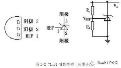
TL431 is a controllable precision voltage regulator source produced by Texas Instruments. The real object is shown in Figure 2-3. Its output voltage can be arbitrarily set to any value ranging from 2.5V to 36V with two resistors. The typical dynamic impedance of the device is 0.2Ω, which is used in many applications to replace zener diodes, such as digital voltmeters, op amp circuits, adjustable voltage power supplies, and switching power supplies. Figure 2-2 shows the wiring diagram of TL431 pin arrangement and use.
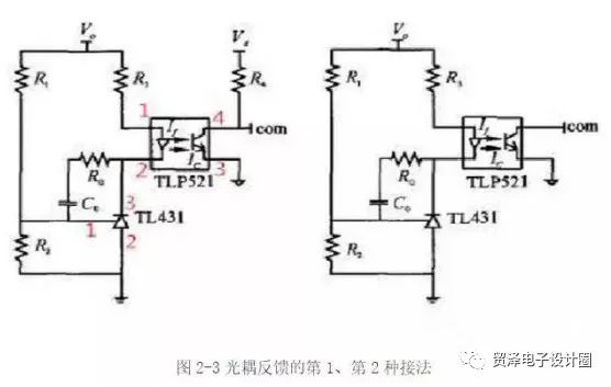
The first optocoupler connection method. Vo is the output voltage, and Vd is the power supply voltage of the chip. The com signal is connected to the output pin of the chip's error amplifier. Note that the ground on the left is the output voltage ground, and the ground on the right is the power supply voltage ground for the chip. The working principle of the connection shown in Figure 2-3 is as follows: when the output voltage increases, the voltage of pin 1 of TL431 (equivalent to the reverse input terminal of the voltage error amplifier) ​​rises, and pin 3 (equivalent to the output pin of the voltage error amplifier) ) When the voltage drops, the primary current If of the optocoupler TLP521 increases, the output current Ic at the other end of the optocoupler increases, the voltage drop across the resistor R4 increases, the com pin voltage decreases, the duty cycle decreases, and the output voltage Small; conversely, when the output voltage decreases, the adjustment process is similar.
The form of the potential higher than the inverting terminal utilizes a characteristic of the op amp-when the output current of the op amp is too large (exceeds the output capability of the op amp), the output voltage value of the op amp will decrease, the larger the output current, the output voltage The more drops. Therefore, the circuit using this connection method must connect the two input pins of the error amplifier of the PWM (pulse width modulation) chip to a fixed potential, and the potential at the same terminal must be higher than the potential at the reverse terminal, so that The initial output voltage of the error amplifier is high.
The working principle of the connection shown in Figure 2-3 is: when the output voltage increases, the primary current If increases, the output current Ic increases, because Ic has exceeded the current output capability of the voltage error amplifier, the com pin voltage drops , The duty cycle decreases, the output voltage decreases; conversely, when the output voltage drops, the adjustment process is similar.
The common third connection method is shown in Figure 2-4. Basically similar to the first one, the difference is that an additional resistor R6 is added. The function of this resistor is to inject an additional current into the TL431 to prevent the TL431 from working normally because the injected current is too small. In fact, if the resistance value R3 is appropriately selected, the resistance R6 can be omitted. The adjustment process is basically the same as the 1-connection method.
The common fourth connection method is shown in Figure 2-4. This connection is similar to the second connection. The difference is that an additional resistor R4 is connected between the com terminal and the fourth pin of the optocoupler. Its function is the same as R6 in the third connection. Its working principle is basically the same as the connection. 2.

Feedback methods 1 and 3 are suitable for any duty cycle (turn-on time to cycle ratio), while feedback methods 2 and 4 are more suitable for use in smaller duty cycles.
summary
The optocoupler of the switching power supply mainly isolates, provides feedback signals and switches. The power supply of the optocoupler in the switching power supply circuit is provided from the secondary voltage of the high-frequency transformer. When the output voltage is lower than the voltage of the regulator tube, the signal optocoupler is turned on, and the duty ratio is increased to increase the output voltage; otherwise Turning off the optocoupler reduces the duty cycle, which lowers the output voltage. Once the secondary load of the high-frequency transformer is overloaded or the switch circuit is faulty, there is no optocoupler power supply, and the optocoupler controls the switch circuit to not start vibration, thereby protecting the switch tube from breakdown and burning.
Small Vacuum Cleaner,Cordless Vacuum Cleaner,Handheld Vacuum Cleaner,Portable Vacuum Cleaner
Ningbo ATAP Electric Appliance Co.,Ltd , https://www.atap-airfryer.com