Micro- LEDs are current-driven light-emitting devices that typically operate in two modes: passive location (PM: Passive Matrix, also known as passive addressing, passive addressing, passive driving, etc.) and active Addressing driver (AM: Active Matrix, also known as active addressing, active addressing, active driving, etc.), this article also extends another "semi-active" driver for active drivers. These modes have different driving principles and application features. The following is a detailed description of the principles through circuit diagrams.
What is the PM drive mode?
The passive address drive mode connects the anode of the LED pixels of each column in the array to the Data Current Source, and connects the cathode of each row of LED pixels to the line scan. Line (Scan Line). When a particular Y-th column scan line and X-th line scan line are gated, the LED pixels at the intersection (X, Y) are illuminated. The entire screen can be displayed in a high-speed point-by-point scan in this way, as shown in Figure 1.
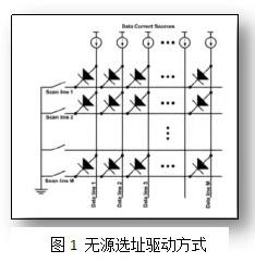
This scanning method is simple in structure and relatively easy to implement.
However, the shortcoming is that the wiring is complicated (requires X+Y root connection), the parasitic resistance and capacitance are large, resulting in low efficiency, and the pixel illumination time is short (1 field/XY), resulting in low effective brightness, easy crosstalk between pixels, and The frequency of the scanning signal is high.
Another optimized passive location driving method is to add a latch in the column scanning portion, and its function is to store the column scanning signals (Y1, Y2 ... Yn) of all pixels in the Xth row at a certain time in advance in the latch. In the device. When the Xth line is gated, the above Y1-Yn signals are simultaneously loaded onto the pixel [3]. This driving method can reduce the column drive signal frequency and increase the brightness and quality of the display screen. However, it still cannot overcome the inherent defects of the passive location selection driving method: the connection is complicated, the crosstalk is easy, and the pixel strobe signal cannot be saved. The active location-driven approach provides a good solution to the above difficulties.
What is the AM drive mode?
In the active addressing drive circuit, each Micro-LED pixel has its own independent drive circuit, and the drive current is provided by the drive transistor. The basic active matrix driver circuit is a two-transistor single-capacitor (2T1C: 2 Transistor 1 Capacitor) circuit, as shown in Figure 2.
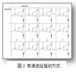
At least two transistors are used in each pixel circuit to control the output current, and T1 is a gate transistor for controlling the on or off of the pixel circuit. T2 drives a transistor that is connected to a voltage source and provides a stable current to the Micro-LED during a frame time. There is also a storage capacitor C1 in the circuit to store the data signal (Vdata). When the scanning signal pulse of the pixel unit ends, the storage capacitor can still maintain the voltage of the gate of the driving transistor T2, thereby continuously driving the current for the Micro-LED pixel until the end of the frame.
The 2T1C driver circuit is only a basic pixel circuit structure of the active-addressed Micro-LED, which is simple in structure and easy to implement. However, since the essence is a voltage controlled current source (VCCS), and the Micro-LED pixel is a current type device, it will bring certain difficulty in the control of display gray scale, which we will later in the "Micro-LED color". It will be discussed in the section on grading and grayscale. Dr. Liu Zhaojun's research group has proposed a 4T2C current-proportional Micro-LED pixel circuit that uses a current-controlled current source (CCCS) to provide advantages in achieving gray scale.
What is the "semi-active" location driver?
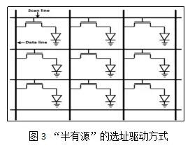
Another need to mention is a "semi-active" location drive method [6]. This driving method uses a single transistor as a driving circuit of the Micro-LED pixel (as shown in FIG. 3), so that crosstalk between pixels can be better avoided.
Led Par Lights ,Led Par Can,Led Mini Flat Par Light,Led Par Can Light
Guangzhou Cheng Wen Photoelectric Technology Co., Ltd. , https://www.cwledwall.com