Switching loss calculation - anti-excitation
1, CCM mode switching loss
The CCM mode differs from the DCM mode in switching loss. The complex CCM mode is explained first, and the DCM mode is very simple.
1.1 Switching losses during turn-on
In CCM mode, the current and voltage waveforms when the switch is turned on are shown in Figure 1.
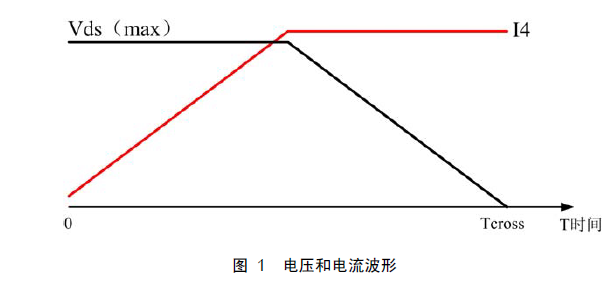
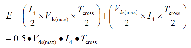
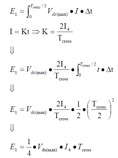
According to the principle given by the data: When the MOS tube is connected to an inductive load, the voltage remains unchanged when the current changes; when the voltage changes, the current remains unchanged. Therefore, the average value of the current and the average value of the voltage can be used to calculate the average switching loss when the MOS transistor is turned on, and the switching loss when the switch is turned on is:
1.1.1 Flyback Switching Power Supply Loss Formula under CCM
1. Determination of I4 current
Let us review the current waveform of the input inductor in CCM mode, as shown in Figure 2.
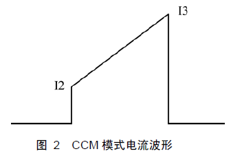
It can be seen from Fig. 2 that I2 is the current when the MOS transistor is turned on, and I3 is the maximum current of the MOS transistor. It is well known that the conversion time of the flyback switching power supply is nanosecond, and the conduction time is microsecond, so I4=I2 in the switching loss formula in conduction.
2. Determination of Vds voltage
The flyback circuit block diagram is shown in Figure 3.
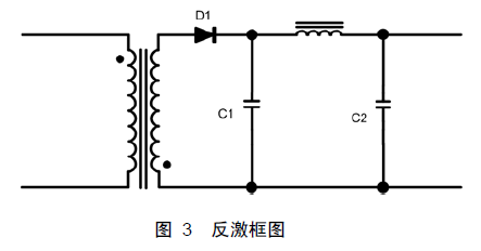
Before determining the Vds voltage, several principles need to be determined:
(1) When there is energy in the transformer, at least one of the input winding and the output winding has a current flowing or both (the current is the performance of the transformer);
(2) The output diode is required to conduct voltage, that is, the voltage of the output winding must rise to Vo+Vf;
(3) The inductor current cannot be abruptly changed.
Since the inductor current cannot be abruptly changed, the output winding must maintain the voltage at which D1 is turned on to cause the current to drop rapidly, and then the output winding voltage direction. Therefore, Vds=Vin+Vor during the turn-on conversion. In CCM mode, the switching loss formula of the MOS tube in the flyback power supply is:
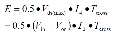
Vor is the reflected voltage on the primary winding.
Again, the flyback power supply in CCM mode, the voltage in the calculation formula of the switching loss when the MOS transistor is turned on is (Vin+Vor), and the current is the minimum current I2.
1.2 Switching loss at turn-off
The voltage and current waveforms during the turn-off conversion are shown in Figure 4.
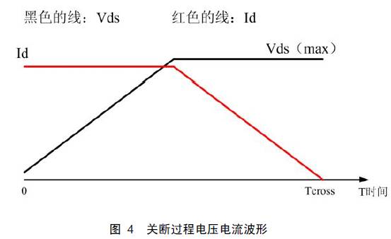
According to the principle given by the data: When the MOS tube is connected to an inductive load, the voltage remains unchanged when the current changes; when the voltage changes, the current remains unchanged. Therefore, the average value of the current and the average value of the voltage can be used to calculate the average switching loss when the MOS transistor is turned off, and the switching loss when the switch is turned off is:
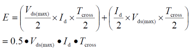
It is very familiar with the switching loss when the previous calculation switch is turned on. It is indeed different.
Current
In a normal flyback switching power supply design, the switching power supply is switched on for nanoseconds, and the on-time is microsecond, so Id=I3 (current I3) in the switching loss formula at turn-on. as shown in picture 2).
2. Voltage Vds
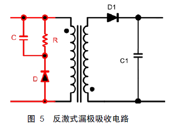
First, a flyback drain spike voltage sink circuit, as shown in Figure 5, in the red part.
Before determining the Vds voltage, several principles need to be determined:
(1) When there is energy in the transformer, at least one of the input winding and the output winding has a current flowing or both (the current is the performance of the transformer);
(2) The output diode is required to conduct voltage, that is, the voltage of the output winding must rise to Vo+Vf;
(3) The inductor current cannot be abruptly changed.
According to the above three principles, the voltage of the output winding first rises to Vo, and then the output rectifier D1 is turned on. At this time, the primary inductor current drops sharply, and the output winding current rises accordingly. The primary leakage inductance spike voltage rise speed is smaller than the nanosecond level, so it can be concluded that the voltage in the calculation formula of the switch off process loss should be the sum of the input voltage and the voltage across the capacitor C.
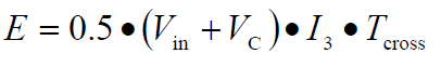
Vc is the absorption voltage of the capacitor in the voltage spike circuit, which includes not only the reflected voltage but also the peak voltage caused by the leakage inductance. I3 is the peak current above the input inductor.
2. Switching loss in DCM mode
The DCM mode is the crossover phase loss with almost no turn-on conversion because the input current at this time is almost zero. But it is still about the loss of the break phase, which is the same as in the previous CCM mode.
This article does not summarize, nor does it list the flyback switching loss formula. Because the results and formulas are not the most important, the key is to understand and how the formula comes out.
SMT Feeder types,
1. different smt machines with different smt feeders, but different model of the same brand machine can use the same feeder,like Panasonic Feeder.
2. Base on the size and types of components, smt feeder could be divided into three types : Tube feeder; Tray Feeder; Bulk Feeder.
Tape feeders with the different size such as 8mm, 16mm, 24mm, 32mm, 44mm, 56mm etc.
3. Base on the feeder condition, smt feeder also could be divided into four types: original new SMT feeder parts, used original SMT feeder parts, imitation/copy new SMT feeder parts, imitation/copy used SMT feeder parts,
Original feeder is made by original smt machine production manufacturers. Due to the large demand for smt feeder, currently there are many copy new feeders parts. Our feeders quality is also very great and looking forward to your cooperation!
Feeder Parts,Smt Feeder Parts,Panasonic Feeder Parts,Parts For Panasonic Feeder
Shenzhen Keith Electronic Equipment Co., Ltd. , https://www.aismtks.com