This article introduces the design of the pyroelectric sensor alarm circuit.
DesignThe pyroelectric sensor alarm circuit is mainly composed of a signal detection circuit, a signal processing circuit and an alarm circuit. The system block diagram is shown below.
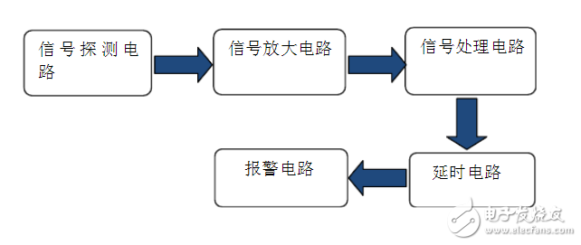
Scheme system diagram
The scheme uses RE200B as the signal detection. When someone moves, the sensor emits an electric signal of about 0.5v, and is rectified and filtered to reach the amplifying circuit. The amplifying circuit is composed of a secondary operational amplifier, and outputs a high level of 3.8v into the signal processing circuit.
The signal processing circuit compares the input signal with the signal from pin 9 through the AND gate. The pin 9 is continuously input to the high level due to the large resistance. Therefore, the signal processing circuit outputs a high level when it detects someone moving. Enter the delay circuit. The delay circuit is composed of a resistor series capacitor. After a fixed period of time, the output electrical signal turns on the triode, and the triode opens the alarm circuit.
Circuit design pyroelectric sensor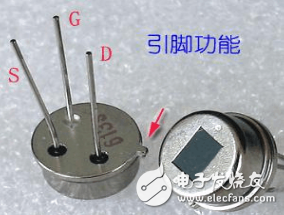
RE200B physical map
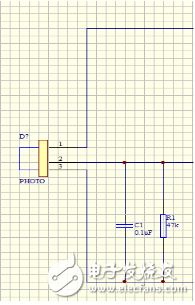
RE200B schematic
The pyroelectric sensor model used is RE200B, which uses the characteristics of pyroelectric material polarization to change the infrared radiation, and cooperates with the dual-sensitivity complementary method to suppress the interference caused by temperature change and improve the stability. It detects the change in infrared energy emitted by the object in a non-contact form and converts it into an electrical signal that is output from pin 2.
The 2-pin output signal, so a 47kΩ resistor and a 0.1uF capacitor are added around it to rectify and filter to eliminate interference.
Biss0001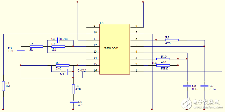
Biss0001 secondary amplification and delay circuit
Biss0001 is a high performance sensing signal processing integrated circuit. Can be set into mating RE200B pyroelectric infrared switch, this test can be quickly turned buzzer. The chip is mainly composed of a secondary operational amplifier circuit, a logic circuit, a lockout time timer, and a delay time timer.
When RE200B detects the movement of the person, the output signal is about 0.4v. After the signal is rectified and filtered by the peripheral resistor and capacitor, it first enters the amplifier circuit inside the biss0001 chip. The amplifier circuit is composed of the second-level op amp. The sensitivity of RE200B is partly affected by the resistors and capacitors on pin 15. The experimental selection of 47kΩ and 47uF aluminum electrolytic capacitors makes the signal transmitted by RE200B relatively stable and the distance reaches 1m. After two stages of amplification, the signal amplitude is 3.8v, and then the signal enters the AND gate and the signal from the 9th pin (because the 9th pin has a large resistance in this test, it is divided accordingly). The voltage, so the 9th pin continues to output high level). The compared output signal arrives at the chip's lockout timer and delay timer. The delay time timer will output a high level for a period of time after receiving the high level. The duration is TX≈49152*R1*C1(s). In this experiment, R1=47kΩ, C1=10nF, and the alarm duration is about 23s. The blocking time timer is not interfered by any external signal within a period of time TI of the delay TX, that is, the chip stops working during this period of time, TI's duration TI≈24*R2*C2(s), this experiment R2= 51kΩ, C2=10nF, and the duration is about 0.012s. After the above process, the signal outputs 3.8v voltage, and after the voltage dividing resistor is turned on, the triode is turned on, thereby triggering the alarm circuit.
Alarm circuit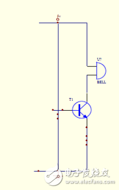
The alarm circuit consists of a power supply voltage, a triode, and a buzzer. The buzzer is connected between the collector of the triode and the positive pole of the power supply voltage (5v). The emitter of the triode is connected to the negative pole of the power supply voltage, and the base is connected to the biss0001 chip. Number pin. When the chip detects the movement of the person, the 3.8v electric signal is output from the pin 2 through the voltage dividing resistor, and then the triode is turned on, thereby triggering the buzzer.
Experimental schematic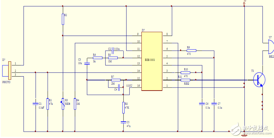
This experiment simulates the design of a pyroelectric sensor alarm. The sensor is model re200b and is equipped with its dedicated chip biss0001 for commissioning. Re200b will output a high level to biss0001 while feeling the movement of infrared light around the human body. At the same time, because the 9th pin is connected to the large resistance fixed input high level, biss0001 detects the signal and outputs a high level to trigger the buzzer. Device.
FM AM Antenna,FM AM Radio Antenna,FM AM Antenna for CAR,Fm AM Antenna Marine,FM AM Antenna for home Stereo
Yetnorson Antenna Co., Ltd. , https://www.yetnorson.com