The original article on filters, bridges, and splitters was intended to introduce a general method, but when writing "How to Design a Band-Pass Filter," someone asked how to design a waveguide filter. The 9th issue of Lange Bridge When the design was asked about how the micro-bridge should be designed, I would like to express here that the principles of several commonly used microwave passive devices are based on the theory of transmission lines. The design principles and methods are universal, and a structure is mastered. The device design method can be extended to similar products in other structures.
Someone suggested that I write some active circuits, but I have limited experience in active circuits. I really need to clearly and accurately express some concepts and find that my experience is still a lot worse. I am also trying my best to reserve active knowledge. I was recently learning a book called "Frequency Synthesizers: Concept to Product". I thought I could use it as part of a microwave notebook. I would like to intersperse some of this book's learning experience in microwave notebooks. Until the completion of this book learning. It is also hoped that this approach will be accepted. This period is still based on the ultra-broadband bridge that I am good at as a transition.
The stripline form of the bridge is relatively easy to achieve ultra-wideband, but also can achieve a strong coupling through the wide-edge coupling structure. It is suitable for strong coupling ultra-wideband bridge structures. We know that the 8343 bridges can be cascaded into a 3dB bridge, so the 8343 Ultrawideband Bridge is very popular in microstrip and stripline structures. In this paper, the design of a stripline UWB bridge is described by an example of a 2 GHz- 18 GHz stripline 8343 ultra-broadband bridge.
1. Structure of stripline UWB 8433 bridge
The principle of the bridge is described in "Implementation of Bezier Waveguide Directional Couplers" and "Lange Bridge Design" and is not repeated here. The structure of the stripline 8343 bridge is shown in Figure 1. Actually consists of three sheets of media. The front and back sides of the middle sheet of media are pictured. The upper and lower media sheets serve as supports.
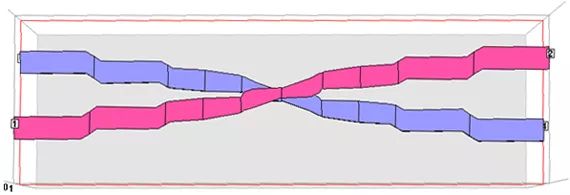
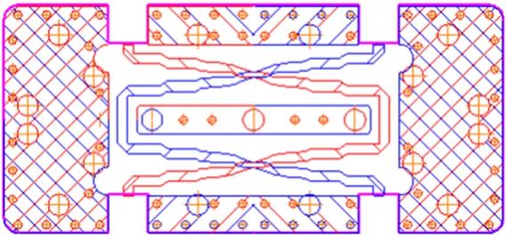
Figure 1, Strip 8343 Bridge and 3dB Bridge Structure
2. Design method of ultra-wideband 8343 bridge
1) Design steps
The bridge is a coupled transmission line coupler. Follow these steps when designing:
· Determine the number of coupled transmission lines and the odd-even mode impedance in accordance with the index look-up table or in circuit simulation software such as ADS · Calculate the physical size of each coupled transmission line based on odd-even mode impedance · Electromagnetic simulation optimization
2) Design Example
a) Establish a model in ADS to determine the number of coupled transmission line sections and odd-even mode impedance
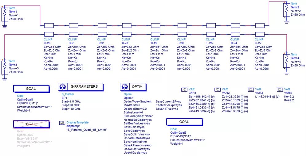
Through the tuning and optimization calculation, the odd-even mode impedance of each coupled transmission line can be obtained in Table 1:
Table 1, odd-even model impedance of coupled transmission lines in each section
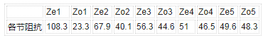
According to personal habits, choose rogers5008 Er=2.2 as stripline media. The intermediate medium thickness t=0.127mm, the upper and lower medium thickness t=0.762mm, and the physical dimensions of the actual coupled transmission line are calculated in a polar SI9000 or other transmission line calculation tool. Taking Ze1=108.3 and Zo1=23.3 as examples, see FIG. 1 . b) Calculate the physical dimensions of each coupled transmission line using odd-even mode impedance
Figure 2, the parity mode into physical size
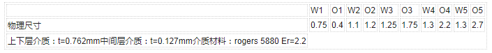
Since the 8343 coupler is strongly coupled, a wide-side coupling structure must be used in the stripline as shown in Figure 2. The calculation is based on an iterative experience. In Chapter 3 of the Microstrip Circuit, the conclusion is that (Ze+Zo)/2=Z0 in the section of the coupled microstrip line. Odd-mode and even-mode and divide-by-2 equal to a single root. The characteristic impedance of the line). First, calculate the line width based on the impedance of a single line, and then adjust the distance between the two lines to achieve the desired parity mode. Usually the even mode is determined by the width of the transmission line and the thickness of the upper and lower support media. The odd mode is determined by the media thickness of the intermediate layer, the width of the transmission line, and the degree of overlap of the two transmission lines. After calculation, the theoretical odd-even mode impedances are converted into the actual stripline physical dimensions. The data is shown in Table 2.
Table 2. Actual physical dimensions of coupled lines obtained from odd and even modes
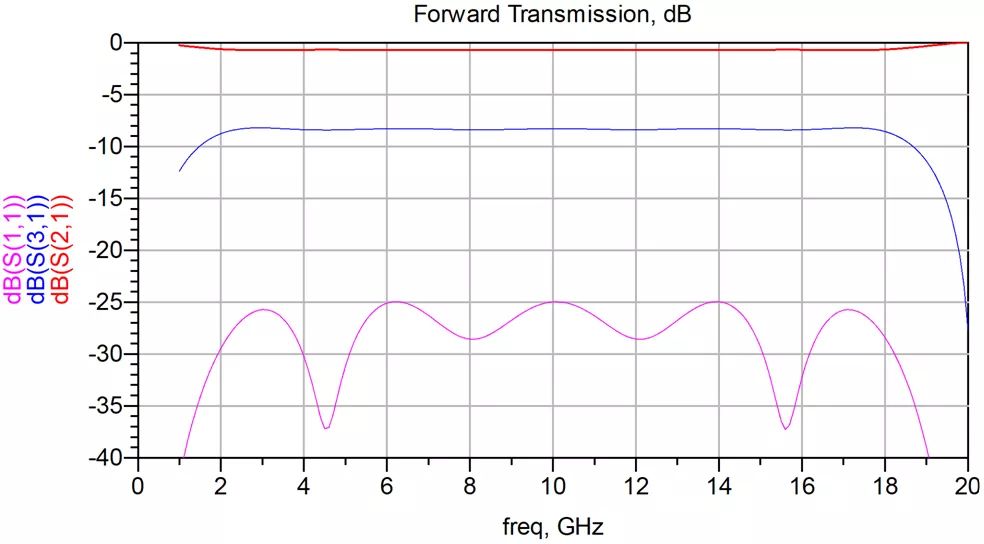
With the actual physical size, electromagnetic field simulations can be performed to verify that the actual coupler model in the sonnet and the results of the direct simulation are shown in Figure 3. It can be seen that the parameters given by the theory are very accurate. For the purpose of simulating the fast grid accuracy of 0.05, if the grid can be subdivided for the pursuit of accuracy, or by dividing the circuit into multiple sub-circuits for precise design. c) Electromagnetic simulation optimization
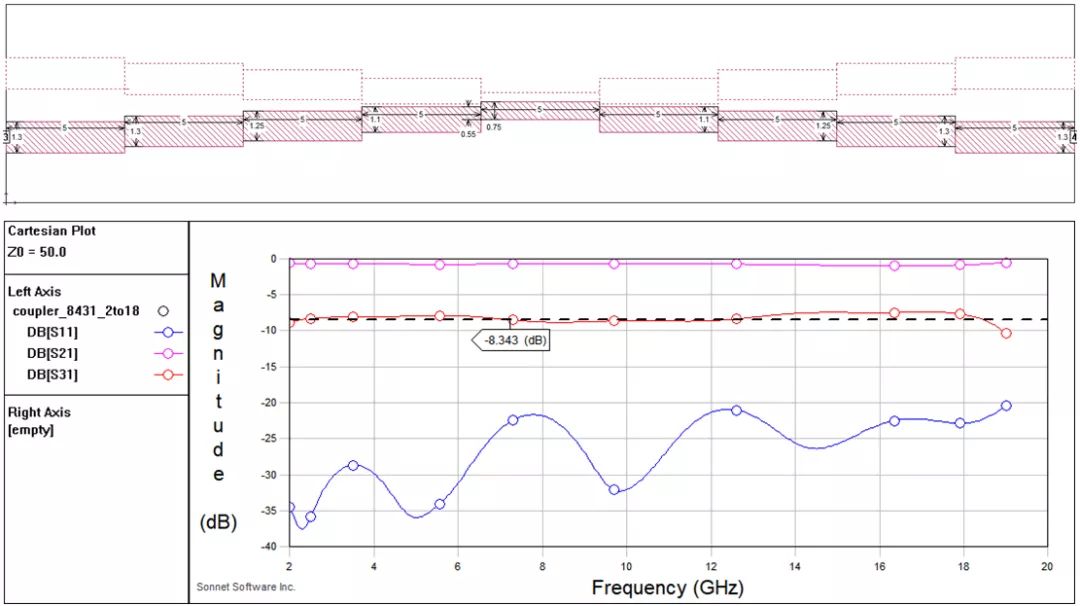
Figure 3, stripline wideband coupler model without folding
The structure shown in FIG. 3 is a reverse directional coupler, which is not conducive to cascading a 3 dB coupler, so the coupler needs to be folded as shown in FIG. The folded coupler straight path and the coupling path are in the same direction. This coupler is convenient for cascade formation. The 3dB coupler is shown in Figure 1.
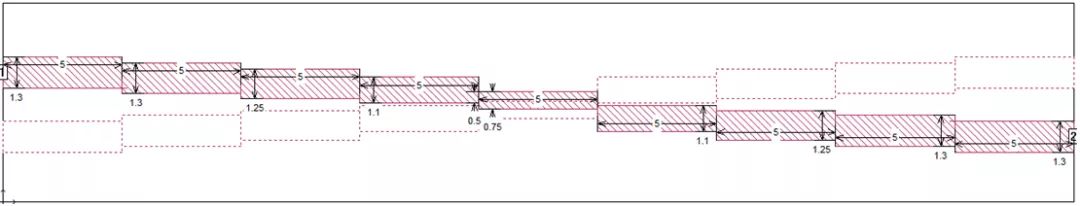
Figure 4. Folding wideband coupler model
After folding, if the middle section is not subjected to special treatment, the symmetry of the coupler will be damaged, and it is not necessary to deal with it if it is acceptable. However, if the pursuit is perfect, the middle section can be properly symmetrically cross-processed. The effect of the symmetrical crossover on the odd-even mode parameters of the middle section can be determined by the odd-even mode parameter extraction method described in the 9th edition of “lange bridge designâ€.
A new rule from the Drug Enforcement Administration (DEA) threatens to upend the American hemp industry, and could even result in criminal prosecutions for manufacturers of CBD and delta-8 THC products.
The DEA says the [interim final rule," issued Aug. 20, is simply a matter of adjusting its own regulations to account for changes to the Controlled Substances Act that were mandated by the 2018 Farm Bill (or Agricultural Improvement Act) that legalized hemp and CBD production. The new rule [merely conforms DEA`s regulations to the statutory amendments to the CSA that have already taken effect," says the agency. The new rule doesn`t break any ground, according to the DEA.
But many experts on cannabis and hemp law say the DEA rule creates a potential pathway the law enforcement agency could use to prosecute hemp processors and producers of CBD (cannabidiol) and delta-8 THC (or Δ8THC) products. There are two issues: partially processed CBD, and [synthetically derived" delta-8 THC.
Cbd Pod System Oem,Cbd Vape Pod Oem,Best Cbd Pod System,Cbd Pod System
Shenzhen MASON VAP Technology Co., Ltd. , https://www.cbdvapefactory.com