Zener Diod Zener Diodes
A principle: it works in the voltage reverse breakdown state, when the reverse voltage reaches and exceeds the stable voltage, the reverse current suddenly increases, and the voltage across the diode is constant
Category B
From the regulation of high and low points: low voltage regulator diode (<40V);
High Voltage Zener Diode (>200V)
From the material: N type; P type
C. Main parameters
1 stable voltage VZ: In the specified voltage regulator, reverse operating current IZ, the corresponding reverse operating voltage.
2 stable current IE
3 dynamic resistance rZ;
4 Maximum Dissipation Power PZM
5 Maximum stable operating current IZmax and minimum stable operating current IZmin
6 temperature coefficient at, the higher the temperature, the greater the error in the regulator
D. Use
1 Clamp protection for drain and source
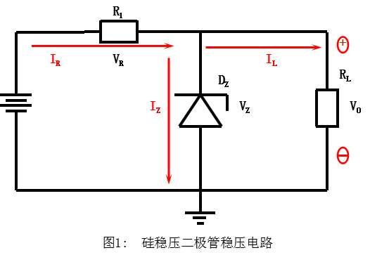
Silicon Zener diode regulator circuit
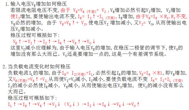
It is regulated by the reverse breakdown characteristic of the zener diode. Since the reverse characteristic is steep, a large current change will only cause a small voltage change.
Transient Voltage Suppressor TVS (Transient Voltage Suppressor)
1. Features:
Under the specified reverse application conditions, when subjected to a high-energy transient overvoltage pulse, its working impedance can immediately drop to a very low conduction value, allow large currents to pass, and clamp the voltage to a predetermined level, thereby effectively Protect the precision components in electronic circuits from damage. Reflected speed (pS level), small size, low clamping voltage, high reliability Bidirectional TVS is suitable for AC circuits, and unidirectional TVS is generally used for DC circuits.
2. Classification:
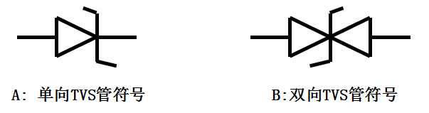
Divided into two types: unipolar and bipolar
3. Symbol: Symbol
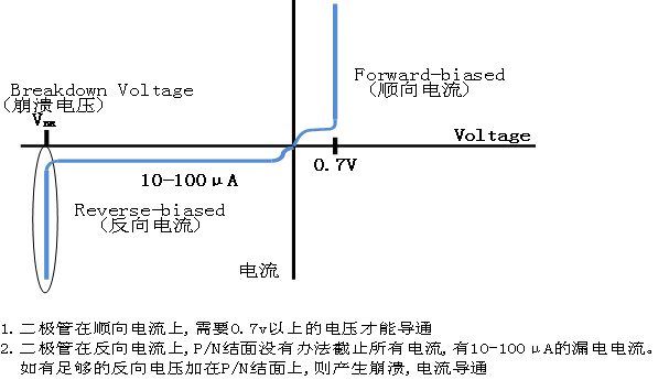
4. Diode Characteristics Chart
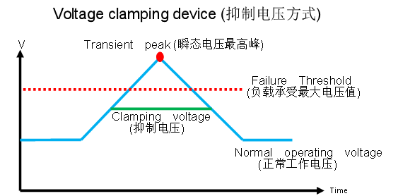
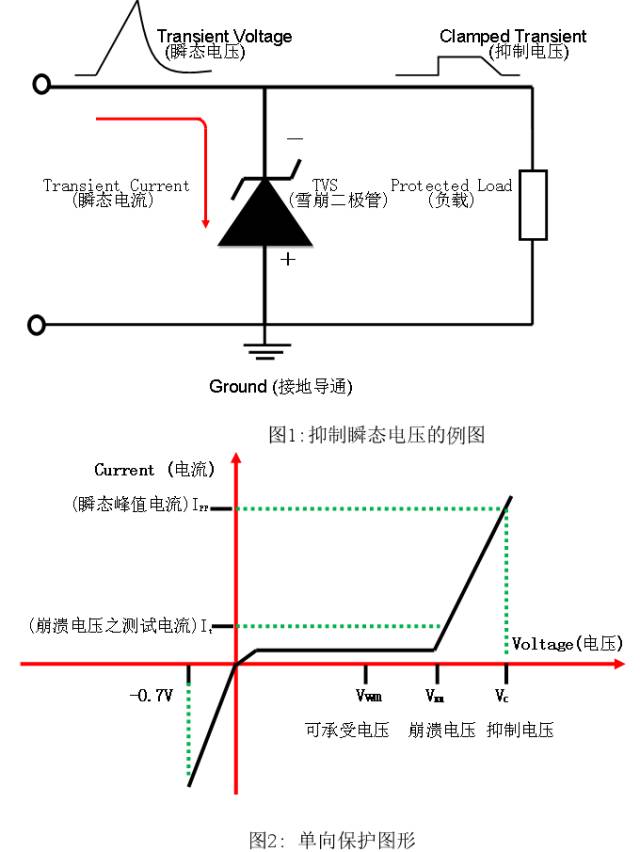
5. Diode suppression example of transient voltage and unidirectional protection pattern
6. The main parameters of TVS
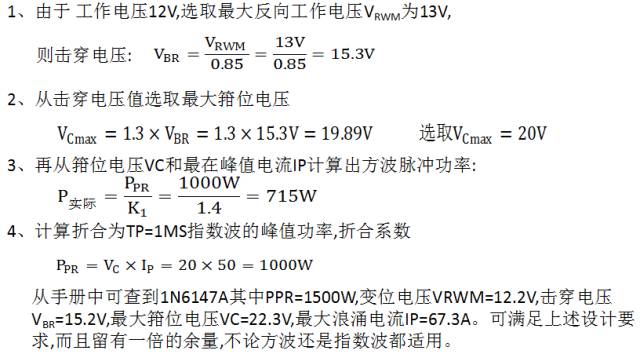
1 VBR: Reverse Breakdown Voltage
Definition: When the TVS flows through the specified 1mA current (IR), the voltage VBR between the two TVS poles of the German TVS is the minimum avalanche voltage of the TVS. At 25°C, before this voltage, TVS is non-conducting. When the transient voltage exceeds VBR, the transient voltage suppressing diode will collapse to suppress the transient voltage to a certain level, providing a very low resistance path for the transient current. This allows transient currents to be diverted through the transient voltage suppression diodes, bypassing the protected components.
2 IR: Reverse Leakage Current
When the maximum reverse working voltage is applied to the TVS, the TVS tube has a leakage current IR, which typically has a reverse leakage current of 10-100 μA. This leakage current is an important parameter when TVS is used in high-impedance circuits.
3 VRWM: Reverse Stand-off Voltage is the voltage across the device at the specified IR when the device is operating in reverse. At this time, the diode is in the non-conducting state, usually VRWM=(0.8~0.9)VBR. When used, VRWM should not be lower than the normal operating voltage of the device or circuit being protected.
4 VC(max ): Maximum clamp voltage (TVS diode Clamping Voltage: Suppression voltage)
Under the pulse peak current Ipp, the maximum voltage across the device is called the maximum clamping voltage. When used, make VC(max) not higher than the maximum allowable safety voltage of the device being protected. The ratio of the maximum clamp voltage to the breakdown voltage is called the clamp coefficient. That is, the clamping coefficient = VC(max)/VBR general clamping coefficient is about 1.3.
5 Cj: TVS diodeJunction Capacitance
The capacitance of the TVS is determined by the area of ​​the silicon wafer and the bias voltage. Under the condition of zero bias, the capacitance of the TVS decreases as the bias voltage increases. The size of the capacitor affects the response time of the TVS device. The larger the capacitance of the transient voltage suppressing diode, the greater the interference to the circuit, the greater the noise formation or the greater the attenuation of the signal strength. For circuits with higher data/signal frequencies, the capacitance value is not more than 10pF.
6 IPP: Maximum peak pulse current.
In reverse operation, the maximum pulse peak current that the device is allowed to pass under the specified pulse conditions.
7 PPR: Reverse pulse peak power.
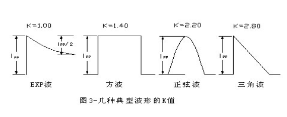
The PPR of the TVS depends on the pulse peak current IPP and the maximum clamp voltage VC, and is related to the pulse waveform, the pulse time, and the ambient temperature.
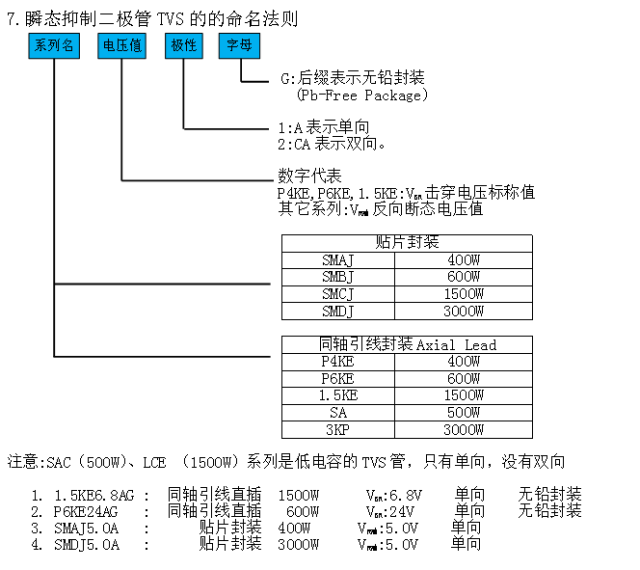
7. TVS TVS nomenclature
8. Detection of diodes
Use a multimeter R×1k to measure the quality of the pipe
For a unipolar TVS, the positive and negative resistances can be measured according to the method of measuring a common diode. The forward resistance is generally about 4k5, and the reverse resistance is infinite.
2 pairs of bipolar TVS, arbitrary red and black table pens to measure the resistance between the two pins should be infinite, otherwise, declare the function of the tube is bad or has been damaged.
9. Typical examples of TVS in circuit applications:
DC selection example:
The DC operating voltage of the whole machine is 12V, the maximum allowable safety voltage is 25V (peak), the impedance of the surge source is 50MΩ, the interference waveform is square wave, TP=1MS, and the maximum peak current is 50A.
AC circuit application example:
The DC line uses a unidirectional transient voltage suppression diode, while the AC must use a bidirectional transient voltage suppression diode. AC is the voltage of the grid. The transient voltage generated here is random, and sometimes there is a lightning strike (transient voltage due to lightning induction). Therefore, it is difficult to quantitatively estimate the instantaneous pulse power PPR. However, there must be a correct selection of the maximum reverse voltage. The general principle is to multiply the AC voltage by 1.4 times to select the maximum reverse voltage of the TVS tube. DC voltage is selected from 1.1 to 1.2 times the TVS tube maximum reverse voltage VRWM. The figure below shows the principle of a computer power supply using TVS for line protection
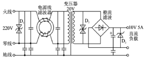
1. Add TVS tube at the 220VAC line incoming line to suppress spike interference in 220V AC power grid.
2. Add the interference filter to the incoming line of the transformer to filter out the small spike interference.
3. Add a TVS tube at the VAC=20V output of the transformer and suppress the interference again.
4. When the DC 10V output is added, TVS tube is added to suppress the interference.
Innosilicon is a worldwide one-stop provider of high-speed mixed signal IPs and ASIC customization with leading market shares in Asian-Pacific market for 10 consecutive years. Its IP has enabled billions of SoC's to enter mass production, covering nodes from 180nm to 5nm across the world`s foundries including: GlobalFoundries, TSMC, Samsung, SMIC, UMC and others. Backed by its 14 years of technical expertise in developing cutting-edge IPs and ASIC products, Innosilicon has assisted our valued partners including AMD, Microchip and Microsoft to name but a few, in realizing their product goals.
Innosilicon team is fully devoted to providing the world's most advanced IP and ASIC technologies, and has achieved stellar results. In 2018, Innosilicon was the first in the world to reach mass production of the performance-leading GDDR6 interface in our cryptographic GPU product. In 2019, Innosilicon announced the availability of the HDMI v2.1 IP supporting 4K/8K displays as well as our 32Gbps SerDes PHY. In 2020, we launched the INNOLINK Chiplet which allows massive amounts of low-latency data to pass seamlessly between smaller chips as if they were all on the same bus. With a wide range of performance leading IP in multiple FinFET processes and 22nm planar processes all entering mass production, Innosilicon's remarkable innovation capabilities have been proven in fields such as: high-performance computing, high-bandwidth memory, encrypted computing, AI cloud computing, and low-power IoT.
Innosilicon Mining Machine:Innosilicon T2 Turbo 25T,Innosilicon T3+ 52T,Innosilicon T3 43T,Innosilicon T2 Terminator,Innosilicon T3 39T,Innosilicon T2 Turbo+ 32T
Innosilicon Mining Machine,T3 Pro Miner,T3 Pro Innosilicon,T3 Pro 67T Innosilicon
Shenzhen YLHM Technology Co., Ltd. , https://www.sggminer.com