The electrical schematic diagram is a representation of the relationship between the electrical working principle of the equipment and the functions of the various electrical components. The use of electrical schematics and techniques is very useful for analyzing electrical circuits and troubleshooting machine circuit faults. The electrical schematic diagram generally consists of main circuit, control circuit, protection, and distribution circuit.
First , the multi-line representation of the circuit and single-line representation 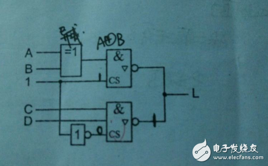
1. Multi-line representation: Each line or wire is represented by a single line.
Features: It can express the content of each phase or each line in detail, especially in the case of asymmetry of each phase or line content.
2. Single-line representation: Two or more connecting lines or wires, using only one line.
Features: Suitable for three-phase or multi-line basic symmetry.
3, mixed representation: part of a single line, part of a multi-line.
Features: It has the characteristics of simple and refined single-line representation, and has the advantages of multi-line representation for describing objects accurately and fully, and because of the coexistence of two representations, change and flexibility.
Centralized representation and separate representation of two electrical components 
1. Centralized representation: A method of drawing graphical symbols of each component of a project in a device or a complete set on a simplified diagram.
Scope and characteristics: a simple map. The components are connected to each other by mechanical connecting wires (dashed lines). The connecting line must be a straight line.
2. Semi-centralized representation: In order to make the circuit layout of the device and device clear and easy to identify, the graphical symbols of some parts of a project are arranged separately on the simplified diagram, and the mechanical connection symbol is used to indicate the relationship between them.
Mechanical cables can be bent, branched and crossed.
3. Separate representation: In order to make the circuit layout of the device and device clear and easy to identify, the graphical symbols of some parts of a project are arranged separately on the diagram, and only the project code is used to indicate the relationship between them.
The amount of information given by the separate representation and the graph using the centralized representation or the semi-centralized representation is equal.
4, the comparison of the three methods
5, the project code numbering method
(1) Components drawn using centralized and semi-centralized representations whose project code is marked only once next to the symbol and aligned with the mechanical connection.
(2) Components drawn by separate representations whose project code should be marked next to the symbol in each part of the project.
(3) The location of the project code should be as close as possible to the top of the graphic symbol, especially the third paragraph (type code) of the project code is near the center of the symbol.
(4) When the circuit is horizontally arranged, the project code is marked above the symbol. When the circuit is vertically arranged, the project code is marked on the left of the symbol. The project code is written horizontally, from top to bottom or left to right.
(5) The terminal code in the project code is marked next to the terminal or terminal position.
(6) For functional units and structural units with a frame, the project code is marked above or to the left of the enclosure.
(7) In most cases, the high-level code in the project code can be marked in the title bar or the label of the project code next to the simplified symbol above the drawing.
Three electrical component contact position, working state and technical data representation 
1. There are two types of contacts: one is electromagnetic contact or manual contact (contactor, electric relay, switch, button, etc.); the other is non-electrical and non-manually operated contacts (non-electrical relay, Contact for stroke switch, etc.).
2. The contact indicates:
(1) Contact symbols of contactors, electric relays, switches, buttons, etc., in the same circuit, after power-on and stress, the direction of action of each contact symbol should be oriented consistently, when the contacts have retention and blocking This is even more the case with the delay function.
(2) For non-electrical and non-manually operated contacts, the mode of operation must be indicated near its contact symbol. Represented by graphics, operating device symbols, and notes, tags, and tables.
3. Representation of the operational state of components: The movable parts of components, devices, and equipment should generally be in a state or location that is not energized or inoperative.
(1) The relay and contactor are in a non-energized state;
(2) The circuit breaker, load switch and disconnector are in the off position;
(3) The manual control switch with zero position is at the zero position, and the manual control switch without zero position is at the position specified in the figure;
(4) The correspondence between the working state of the mechanical operation switch and the working position should generally be indicated in the vicinity of its contact symbol or with additional instructions.
The accident, standby, alarm and other switches shall indicate the position where the equipment is normally used. The components of the multiple opening and closing devices must be represented in mutually consistent positions regardless of the working state of the circuit.
4. Labeling method of component technical data: The technical data of electrical components is generally marked near the graphic symbol. When the connecting lines are arranged horizontally, they are marked as below under the graphical symbols, and when they are vertically arranged, they are marked below the project code; they can also be marked in box symbols or simplified outline symbols.
5. Representation of comments and signs
(1) Two methods of annotation: place it directly near the object to be described and place the annotation elsewhere in the diagram.
(2) If there is an information mark on the equipment panel, the same mark should be added next to the graphic symbol of the relevant component.
Representation method of four- element terminal 
1. Terminal: A conductive element used to connect an external conductor in an electrical component. Terminal classification: fixed terminal and detachable terminal. Fixed terminal graphic symbol: 0 or ·; Removable terminal graphic symbol: Φ 2. Principles and methods for marking terminal blocks with alphanumeric symbols (1) The two end points of a single component are represented by two consecutive numbers. The middle terminals of a single component are represented by numbers in naturally increasing numbers. (2) The same component group 1 is preceded by a letter, such as the letter U1, V1, W1 of the three-phase communication system.
2 If there is no need to distinguish between different phases, the numbers 1.1, 2.1, and 3.1 are available.
(3) Similar component groups
(4) Marking of electrical terminals connected to specific conductors. See the table below and the figure.
3. Labeling method of terminal code
(1) Terminal designations for resistors, relays, analog and digital hardware shall be marked outside the outline of their graphical symbols. The function and annotations of the part are marked in the symbol outline.
(2) Terminals should be marked for each connection point of the connection device used for field connection, test and fault finding.
(3) In the functional unit or structural unit with a frame, the terminal code must be marked in the enclosure to avoid misunderstanding.
Five connecting lines: On the electrical diagram, the interconnection between various graphic symbols.
1, the representation of the wire
2. The thickness of the line: the main circuit of the power supply, the primary circuit, the main signal path, etc. are thick lines, and the rest of the line is thin.
3. Grouping of connecting lines: busbars, buses, distribution harnesses, multi-core wires and cables, etc. can be regarded as parallel connecting lines. For multiple parallel connection lines, they should be grouped by function. If they are not grouped by function, they can be grouped arbitrarily. There are no more than three groups in each group. The group spacing is greater than the distance between lines.
Connection line mark: The mark is generally placed above the connection line, or placed at the break of the connection line, and if necessary, information on the signal characteristics can be marked on the connection line.
4, the representation of the wire connection point
(1) T-shaped connection points can be added with solid dots (·);
(2) Add a solid dot (·) to the + shape connection point;
(3) For the two connecting lines that are not connected but not connected, solid dots should not be added at the intersection, and the direction should be avoided at the intersection, and the connecting points through other connecting lines should be avoided.
Continuous representation and interrupt representation of six connecting lines
1. Continuous representation of the connecting line represented by a single line
2. Interrupt representation method of the connection line
(1) When the connecting line passing through the drawing is long or passes through a dense area, the connecting line is allowed to be interrupted, and the corresponding mark is added at the interruption.
(2) The same line group can be represented by an interrupt line, and the appropriate mark is added to both ends of the interrupt.
(3) A line needs to be connected to another figure, it must be represented by an interrupt line
(4) A symbol mark indicates the interruption of the connection line.
Seven- wire identification mark and its labeling method
1. Identification mark of the wire: marked on both ends of the wire or harness, if necessary, marked on the visible part of its full length (or marked on the line) to identify the mark of the wire or harness.
2. Main mark: A mark system that only marks the characteristics of a wire or a wire harness regardless of its electrical function. The main mark is divided into three types: a dependent mark, an independent mark, and a combination mark.
3. Subordinate mark: A marking system for a wire or harness based on the mark of the terminal to which the wire is connected or the mark of the device to which the wire harness is connected. The subordinate mark is divided into three types: the slave end mark, the slave far end mark, and the slave end mark.
(1) Subordinate local mark: The marking of the wire or harness terminal and the marking system of the terminal or equipment part to which it is connected.
(2) Slave far-end mark: A mark system in which the wire or harness terminal is marked with the same terminal or device component as the remote end.
(3) Subordinate two-end mark: Each end of the wire or the wire harness is marked with a terminal mark connected to the local end and a tag of the madman connected to the distal end or a marking system of the device parts at both ends.
Interrupt line slave tag example
4. Independent marking: A marking system for a wire or harness that is independent of the marking of the terminal to which the wire is connected or the marking of the device to which the wiring harness is attached. The two wires are labeled 1 and 2, respectively, regardless of the terminal markings at both ends. This marking method is only used in the electrical wiring diagram indicated by the continuous line mode.
5. Combination mark: A mark system used together with a separate mark and a separate mark. The combination mark used by the local end mark and the independent mark, the two wires are respectively labeled as A1-1-Ba\A3-2-Bd.
6. Supplementary mark: It is generally used as a supplement to the main mark and is based on the electrical function of each wire or harness. Supplemental marks are usually represented by letters or specific symbols. To avoid confusion, the supplementary mark and the main mark are separated by a symbol.
Basic features and uses of the eight system diagrams and block diagrams
1. System diagram and block diagram: A schematic diagram showing the basic composition, interrelationships, and main features of a system or sub-system, using symbols or annotated boxes. 2. The commonality between the system diagram and the block diagram: they are all represented by symbols or annotated boxes. Difference: The system diagram is usually used to indicate the system or the complete set of equipment, and the block diagram is usually used to indicate the subsystem or equipment; if the system diagram is marked with the project code, it is generally the high-level code. If the block diagram is marked with the project code, it is generally the type code. 3. The role of the electrical system diagram and block diagram: (1) As the basis for further preparation of detailed technical documents. (2) For reference during operation and maintenance. (3) Provide the relevant departments with an overview of the overall plan, brief working principle and main components of the design object.
Basic principles and methods for drawing nine system diagrams and block diagrams
1, the use of graphical symbols (1) the use of box symbols: box symbols represent the combination of components, equipment, etc. and their functions, neither the components, equipment details, nor a simple graphical symbol of all connections.
(2) Use annotated boxes: The boxes in the system diagrams and block diagrams may be a system, subsystem, kit, or functional unit, with an annotated box to represent the object. The form of the box has a solid line frame and a dotted line frame, and the dot-dash line box contains a large capacity, as shown in the figure.
2. Hierarchical division: higher-level system diagrams and block diagrams can reflect the overview of objects; lower-level system diagrams and block diagrams can express objects in more detail.
3. Labeling method of project code (1) On the system diagram and block diagram, each box is marked with the project code. (2) The higher-level system diagram is marked with a high-level code; on the lower-level block diagram, the type code is marked. (3) Since the system diagram and block diagram do not specifically indicate the actual connection line and installation location of the project, the terminal code and location code are generally not marked. (4) The project code is marked above or above the boxes. 4, the connection line representation method (1) connection method: when drawing with a dotted line frame, the connection line is connected to the graphic symbol in the box, when using the box symbol or the annotated solid line frame, then The cable is connected to the outline of the frame. (2) Connection line type: wire connection line - thin solid line power circuit and main signal circuit - thick solid mechanical connection line - dotted line (3) signal flow direction: system diagram and block diagram layout, clear and conducive to identification The flow of processes and information. The flow of control signals is plotted perpendicular to the flow of the process. The open arrows indicate the flow of electrical signals on the wires, and the solid arrows indicate the flow of non-electrical processes and information. (4) Labeling of related content on the connection line: On the system diagram and block diagram, add various forms of comments and explanations as needed.
The basic characteristics and main uses of the ten circuit diagram
1. Circuit diagram: Arranged by graphic symbols and in order of work, detailing the connection relationship of all the basic components of the circuit, equipment or complete set, regardless of the actual position of the schematic.
2, the legend
This circuit diagram illustrates the circuit configuration and operating principle of the power supply, control and interlocking of the compressor, M1 and fan motor M2. This picture has the following characteristics:
(1) Divided into two parts according to the power supply and function: the main circuit is drawn according to the flow of energy (ie current), indicating the power supply relationship between the electric energy through the fuse and the contactor to the motor; the auxiliary circuit is drawn according to the action sequence, ie the functional relationship.
(2) The main circuit is vertically arranged, and the auxiliary circuit is horizontally arranged.
(3) The attached table gives the components and related technical parameters.
3, the use of this map
(1) For the detailed expression and understanding of the working principle of the design object (circuit, device or device), analysis and calculation of circuit characteristics.
(2) As the basis for the preparation of the wiring diagram.
(3) Provide information for testing and finding faults.
High-speed Board-to-board Connectors
High-Speed Board-To-Board Connectors,8 Mm High Board-To-Board Connectors,Pin 10-120Pin Board-To-Board Connectors,High Speed 14Gbps Board-To-Board Connectors
Dongguan SOLEPIN Electronics Co., Ltd , https://www.wentae.com