I have been learning SCM for so long, and I feel that I want to go deeper, but I still have to read assembly language and at least understand the internal structure of SCM.
Let's take ATmega16 as an example to introduce the structure and assembly language of the AVR microcontroller.
CPU core structure of AVR microcontroller
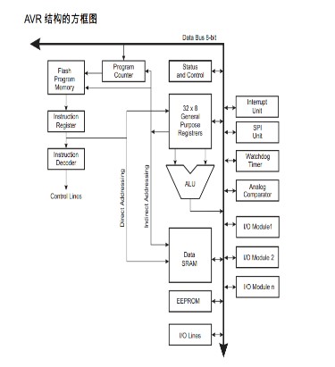
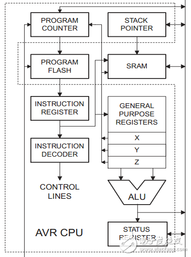
As shown in the above two figures, the left picture is the core structure of the AVR CPU in the dashed box, and the right picture is the block diagram of the AVR single-chip core structure. It can be seen that the data bus (CPU word length) of the AVR single-chip is 8 bits, that is, it is 8 Bit microcontroller.
AVR adopts Harvard structure with independent data and program buses. When the CPU executes an instruction, it fetches the next instruction specified in the PC, forming a first-level pipeline operation mode, which realizes the execution of one instruction in one clock cycle. The data throughput is up to 1MIPS/MHz.
The AVR CPU core consists of several important parts, they are:
A. Arithmetic Logic Unit ALU (Arithmetic Logic Unit)
AVR ALU is directly connected to 32 general-purpose working registers. The ALU operation between the register and the register, between the register and the immediate data only needs one clock cycle. ALU operations are divided into three categories: arithmetic, logic and bit operations. In addition, a multiplier that supports unsigned/signed number and fractional multiplication is provided. The status of the operation result will affect the status register SREG (Status Register).
B. Program counter PC, instruction register and instruction decoder
The program counter PC is used to store the address of the next instruction to be executed in the program memory (ROM) space (pointing to the FlashROM space), the fetched instruction is stored in the instruction register, and then sent to the instruction decoder to generate various control signals, control The operation of the CPU (execute instructions).
The length of an AVR instruction is mostly 16 bits, and a small part is 32 bits. Therefore, the program memory structure of the AVR is actually a word (16 bits) as a storage unit.
The program counter of the ATmega16 microcontroller is 13 bits, which just meets the need for direct addressing of the on-chip 8K words (and 16K bytes) of the Flash program memory space.
C. General Purpose Registers
In AVR, 32 8-bit general-purpose working registers named R0~R31 form a "general fast working register group", which provides operands for ALU. Their RAM mapping space addresses are $0000~$001F, of which 6 registers ($001A-$001F) can be combined into 3 16-bit indirect addressing register pointers, which are called X registers, Y registers, and The Z register is used to indirectly address the data memory (SRAM).
D. Status register-SREG
The status register SREG is an 8-bit flag register, which is used to store the flags related to the status and results after the instruction is executed. The status of each bit is usually automatically generated during the execution of the instruction, but it can also be changed by the user with special instructions as needed.
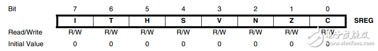
Bit 7-I: Global interrupt enable bit
When the I bit is set, it means that the CPU can respond to interrupt requests, otherwise, all interrupts are disabled. The I bit can be set and cleared by SEI and CLI instructions. After an interrupt occurs, the I bit is cleared by hardware and set by the RETI (return from interrupt) instruction.
Bit 6-T: Bit copy storage
Bit copy instructions BLD and BST use T as the destination or source address. BST copies a bit of the register to T, and BLD copies T to a bit of the register.
Bit 5-H: Half-carry flag The half-carry flag H indicates that a half-carry occurred in an arithmetic operation. This flag is very useful for BCD operations.
Bit 4-S: Sign bit S=N⊕V, S is the exclusive OR of negative sign N and 2's complement overflow sign V
Bit 3-V: 2's complement overflow flag, support 2's complement operation
Bit 2-N: Negative sign indicates that the result of arithmetic or logical operation is negative
Bit 1-Z: The zero flag indicates that the result of an arithmetic or logical operation is zero
Bit 0-C: The carry flag indicates that a carry has occurred in an arithmetic or logical operation
E. Stack Pointer Register SP (Stack Point)
The stack pointer is mainly used to save temporary data, local variables, and interrupt/subroutine return addresses. The stack pointer always points to the top of the stack, and the AVR stack grows downwards, that is, when new data is pushed onto the stack, the value of the stack pointer will decrease.
The two 8-bit registers of &3E ($005E) and $3D ($005D) in the I/O address space constitute the 16-bit stack pointer register SP of the AVR microcontroller, which are SPH and SPL respectively.
The stack pointer points to the data SRAM stack area and must point to an address space higher than 0x60, so the SP pointer is usually set at the highest point of SRAM during initialization.
When the PUSH instruction is used to push data onto the stack, the pointer will decrease by one; when the subroutine or interrupt return address is pushed onto the stack, the pointer will decrease by two.
When using the POP instruction to pop data out of the stack, the stack pointer increases by one; while using the RET or RETI instruction to return from a subroutine or interruption, the stack pointer increases by two.
Water-cooled capacitor is supercapacitor is a capacitor with a capacity of thousands of farads.According to the principle of capacitor, capacitance depends on the distance between the electrode and electrode surface area, in order to get such a large capacitance, as far as possible to narrow the distance between the super capacitor electrode, electrode surface area increased, therefore, through the theory of electric double layer and porous activated carbon electrode.
Water-Cooled Capacitor,Water-Cooled Power Capacitor,Water-Cooled Electric Heat Capacitor,Water-Cooled Electric Heating Capacitor
YANGZHOU POSITIONING TECH CO., LTD. , https://www.cnfudatech.com