Published: 2004-11-21 18:49:40 original author: Lu Tao |
The LM3886 is a mono, medium power, high performance audio power amplifier IC, and is one of the representative ICs of the National Semiconductor (NS) company's "OVerture" audio power amplifier series. It adopts 11-pin TO-220 package and has input mute function, suitable for small active speakers, surround sound amplifiers and high-fidelity stereo TVs as power amplifiers. LM3886 main performance profile 1. Continuous average output power: The most important feature of this IC is that it has complete protection functions without external protection circuits. It contains SPIKe (self-instantaneous temperature) protection circuit developed by NS, which dynamically detects and protects the safe working area (SOA) of the output stage transistors. In order to fully realize the protection functions of overvoltage, undervoltage, overload, output short circuit (including short circuit to ground and short circuit to power supply), thermal runaway and instantaneous temperature shock. Figure 1 is the 3886 internal equivalent circuit. Brief analysis of circuit working principle
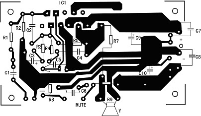
R2 provides the bias voltage for the non-inverting input of LM3886; C2 connected in parallel with the two inputs is used to reduce the high-frequency gain of the amplifier to prevent the output tube from oscillating while suppressing the input electromagnetic interference noise; R5, R4, and C4 form the feedback Loop, the amplifier's low-frequency response and high-frequency corner frequency fH depend on R3, C3; R4, C4, R5 and R3 determine the high-frequency gain and low-pass corner frequency fL (the calculation formula of fH, fL is omitted). C4 is a compensation element, which together with R4 and R5 plays a role in reducing high-frequency gain. R8, R9, C5 and the switch (shown by the dotted line in the figure) form a mute control circuit: when the switch is turned off, the LM3886 stops the output, that is, the mute works; when the switch is turned on, the mute is released, and R8 limits the output current of ⑧ pin to 0.5mA (LM3886 foot current ≥0.5mA). C5 provides a large time constant for mute on and off. The role of R6 and C6 is to prevent the amplifier from generating high-frequency oscillations. The role of L1 and R7: If the load is capacitive (such as a long speaker cable), the amplifier will be overloaded at high frequency and the square wave response will be turned. To avoid this phenomenon, a parallel circuit composed of LR is connected in series at the output At this time, L exhibits a large inductive reactance. A 10Ω resistor isolates the amplifier from the capacitive load and reduces the Q value of the loop formed by L and the capacitive load. At low frequencies, the 10Ω resistor is short-circuited by L, and the amplifier has little inductance L directly drives the load. A few points for attention in self-made The 150W Hi-Fi amplifier circuit introduced in this article is shown in Figure 2. Because the pins of this series of ICs are compatible with each other, the printed circuit board shown in Figure 3 can be installed with either LM3876 (50W) or LM3886 (150W). For this reason, the ⑤ pin of IC1 on the circuit board is connected To the power supply to suit the LM3886, and when installing the LM3876, because the ⑤ pin is the NC terminal (not connected internally), it is still suitable. For best performance, use C7 ~ C10 to decouple the power supply and ground all the ground wires of the circuit board; IC1 is installed on the side of the circuit board to facilitate fixing it on the radiator. Thermal resistance is less than 1.5kΩ / W. The hollow core inductor L1 can be formed by winding 13 turns of? 1mm enameled wire on a? 10mm tire; the resistor R7 is installed in L1, and both ends of them are soldered in parallel on the circuit board. A switch is connected to the MUTE end of this circuit. When the switch is turned off, ICl is in a mute state; if mute is not required, a short-circuit wire should be welded to the MUTE end. R6 ~ C6 are used to improve the high frequency stability of the amplifier, which can usually be omitted, but it is best to add it. The best load of LM3886 (or LM3876) is 8Ω. If it is used for 4Ω load, when the power supply voltage drops to about 27V, the SPIKE protection circuit inside IC1 will work to reduce the output power to about 10W. Therefore, the impedance of the speakers used should not be less than 8Ω. |
Article source: 2004 10 issue of electronic production magazine Editor in charge: ediy |

Follow WeChat

Download Audiophile APP

Follow the audiophile class
related suggestion
'+ data.data.username +' '; dom + ='
HVAC Air Cleaner Purifier, technology with UV Germicidal, Electronic, electrostatic, photocatalyst and photo electronic.
Electronic air cleaners, sometimes referred to as ionizers or electronic air purifiers, use electrically charged filters to reduce the number of airborne contaminants in your home. As air passes through your heating and cooling system, the Electronic Air Cleaner traps large particles (such as dust and dander) in a prefilter. Then, electrically charged filters attract and trap smaller particles (such as bacteria and mold) to prevent them from recirculating through your home.
Control: connected with HVAC system.
Install: Return air, Air Duct, Air Handling Unit, Fan Coil.
Electronic Air Cleaner,Hvac Air Purifier,Air Purifier Hvac,Air Duct Cleaner
Dongguan V1 Environmental Technology Co., Ltd. , https://www.v1airpurifier.com