For pulse amplitude,  For pulse width,
  For the pulse period.
When a rectangular pulse is used as the excitation source of the RC series circuit, different time constants and outputs are selected to obtain a certain output waveform that we want, and the specific relationship between excitation and response.
For a rectangular pulse signal, the response is the voltage taken from both ends of the resistor, ie  , the circuit time constant is smaller than the pulse width of the pulse signal, usually taken
  .
.
And when t = 0,  Mutant to
  And during 0< t < t1 there are:
  , equivalent to a constant voltage source connected to the RC series circuit, which is actually the zero state response of the RC series circuit:
 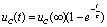 . due to
  , as shown in the circuit of Figure 4-17
  . and so
  , that is: the output voltage has a sudden change from 0 V to
  .
.
because  , so the capacitor is charging very fast. when
  When there is
  ,then
,then  . So in
  During this period, a positive spike signal is output across the resistor, as shown in Figure 4-18.
in  time,
time,  Mutated to 0 V, and
  During the period: = 0 V, which is equivalent to shorting the RC series circuit, which is actually the zero input response state of the RC series circuit:
  .
.
due to  Time,
Time,  Therefore
  .
.
because  Therefore, the discharge process of the capacitor is extremely fast. when
  When there is
  ,Make
,Make  So in During this period, a negative spike signal is output across the resistor, as shown in Figure 4-18.
For a periodic rectangular pulse wave signal, then  It is also a positive and negative spike signal in the same cycle, as shown in Figure 4-18.
The glitch signal is widely used, and is often used as a trigger signal for a flip-flop in a digital circuit; it is often used as a trigger signal for a thyristor in a converter technology.
This output of the sharp pulse wave reflects the result of the input rectangular pulse differentiation, so this circuit is called a differential circuit.
The differential circuit should meet three conditions: 1 the excitation must be a periodic rectangular pulse; 2 the response must be the voltage taken from both ends of the resistor; 3 the circuit time constant is much smaller than the pulse width, ie  .
.
For a rectangular pulse signal, the response is the voltage taken from both ends of the capacitor, ie  And the circuit time constant is greater than the pulse width of the pulse signal, usually taken
  .
.
because  Time,
Time,  At time t=0
  Suddenly rising from 0 V to
  Still
Still  ,
,
Therefore  . in
. in  During the period,
  At this time, it is the zero state response of the RC series state, that is,
 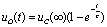 .
.
due to  , so the capacitor is very slow to charge. when Time,
  . When the capacitor has not been charged to steady state, the input signal has changed suddenly, from Suddenly dropped to 0 V. Then at During the period,
  At this time, it is the zero input response state of the RC series circuit, that is,
  .
.
due to  , so the capacitor is from
  The discharge begins. because
  , the discharge is very slow, when the capacitor voltage has not decayed to
  Time,
Time,  Mutations have occurred again and have been repeated. Thus, a sawtooth signal is obtained at the output, as shown in Figure 4-20.
The sawtooth signal is used as a scanning voltage in an electronic device such as an oscilloscope or a display.
It can be seen from the waveforms in Figure 4-20:  The larger the charge and discharge are, the better the linearity of the sawtooth signal is.
As can be seen from the waveforms in Figure 4-20,  is true The result of the integration, so this circuit is called an integration circuit.
The RC integration circuit should meet three conditions: 1 Is a periodic rectangular wave; 2 the output voltage is taken from both ends of the capacitor; 3 circuit time constant is much larger than the pulse width, ie  .
.
The waveform is shown in Figure 4-21(b). Try to draw the output voltage waveform when the following two parameters are drawn. And explain the role of the circuit.
1 when  Time; 2 when
  Time.
Time.
,and so  ,
,
and  Obviously, the circuit is a differential circuit at this time, and its output voltage waveform is shown in Figure 4-22(a).
2 because .
and  , but
, but  Very close to
  . Therefore, the capacitor is charged slowly, that is,
  .
.
Therefore  So when
  Time,
Time,  ,
,  ;
;  Time,
Time,  .
.
at this time,  Has jumped from 10 V to 0 V, then the capacitor is discharged through the resistor, ie
  .
.
and so  .
.
Then  Time,
Time, 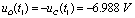 ;
;  Time,
Time,  .
.
The output voltage waveform is shown in Figure 4-22(b). .
As you can see from Figure 4-22: When  The bigger the time,
  The closer the waveform is to Waveform. Therefore, the circuit at this time is called a coupling circuit.
Waveguide Attenuator,Adjustable Rf Attenuator,Waveguide Variable Attenuator,High Power Variable Attenuator
Chengdu Zysen Technology Co., Ltd. , https://www.zysenmw.com