The application research of the power supply network monitoring system of the program-controlled switchboard is more and more concerned by people in this field. At present, commonly used power supply monitoring systems are generally large-scale monitoring systems. This system uses 2Mbit / s port to transmit information, which has high requirements on transmission lines and occupies optical cable resources. Due to the comprehensive monitoring of the power supply of program-controlled switches, the signal collection volume is very large, its structure is complex, the investment cost is high, and the staff's technology The level requirements are also very high, suitable for large-capacity computer rooms, not suitable for power monitoring of many rural small-capacity computer rooms. This article is based on the study of a large-scale program-controlled switchboard power supply monitoring system, and proposes a new type of program-controlled switchboard power supply network monitoring system suitable for a small-capacity computer room.
System hardware circuit design monitoring system consists of on-site monitor, transmission network and central monitor. The on-site monitor has the functions of signal acquisition, judgment, sending, alarming, and receiving control; the central monitor is the control center of the system; the transmission network uses the lines and switching equipment of the telecommunications network.
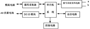
Figure 1 Schematic diagram of the composition of the field monitor
The site monitor is the most important and basic component of the communication power supply network monitoring system in this article, and one must be placed in each monitored computer room. The on-site monitor is composed of a single-chip microcomputer control system and various sensors and control components. The operating parameters and operating status of all monitored objects are monitored, recorded, judged, and alarmed by the on-site monitor. The alarm of the on-site monitor is transmitted by the telephone line, it can actively dial, transmit the alarm information to the monitoring center, and also can call the person in charge for voice alarm. Therefore, the on-site monitor can also work independently without relying on the central monitor. The block diagram of the composition of the field monitor is shown in Figure 1. The field monitor is a single-chip microcomputer control system, which is composed of DC / DC power module, dialing and DTMF transceiver code circuit, voice circuit, general collector, control circuit and so on.
The transmission network between the central monitor of the monitoring system and each field monitor is connected by dialing using the existing telecommunications telephone network. The schematic diagram of system networking is shown in Figure 2.
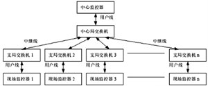
Figure 2 Schematic diagram of system networking
The central monitor is composed of a host, a display, a speaker keyboard, a mouse, a printer, and an interface circuit. The functions of the central monitor are: receiving alarm information from the on-site monitor, forming a screen display, sound alarm, and storing fault information; monitoring to the site The controller sends control information; sets the parameters of the on-site monitor; checks the on-site power parameters, and also has the functions of querying, statistics, printing, and reporting of historical faults.
1 SCM system design
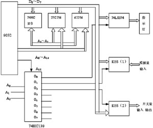
Figure 3 Schematic diagram of the single-chip system
The on-site monitor is controlled by MCS51 series single-chip microcomputer. The block diagram of the single-chip microcomputer system is shown in Figure 3. CPU chip adopts 8032 single chip microcomputer, peripheral expansion circuit adopts 74HC373 as address latch, program chip adopts 27C256, and external memory adopts 62256. Use 74HC138 decoder as address decoding, respectively select one 74LS374 and two 8255, 74LS374 as control indicator light output. 8255 (1) is used for analog input control, and 8255 (2) is used for switch input and output control.
2 AC and DC current collection AC and DC current collection, first of all, through the AC and DC transformers to convert the current signal into a 0 ~ 5V DC voltage signal, and then after voltage conversion, converted to A / D converter (AD574A) The required voltage signal (0 ~ 10V), its circuit block diagram is shown in Figure 4.
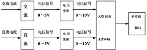
Figure 4 Circuit schematic diagram of AC and DC current acquisition
3 Digital signal acquisition circuit Digital signal acquisition is firstly made by various sensors such as smoke detectors, infrared detectors, water immersion detectors, etc., and the measured physical quantity is turned into a switch electrical signal, and then isolated and leveled Conversion, output to 8255A, and then read by the microcontroller, its circuit schematic is shown in Figure 5.

Figure 5 Schematic diagram of digital signal acquisition circuit
System software design System software mainly includes two parts: the central monitor software design and the field monitor microcontroller software design.
The central monitor host software uses Delphi programming, runs under Windows98, 2000, XP, NT operating systems, the program uses modular design, uses dynamic link library programming, serial communication uses multithreading (serial port interruption), the database uses SQL database system .
The software function of the central monitor interface circuit mainly completes the process of communicating with the central monitor microcomputer. The central monitor interface circuit communicates with the microcomputer through the RS232 interface. If there is an on-site monitor alarm, the interface circuit sends an alarm message to the microcomputer; if the central monitor sends a command to the on-site monitor, the interface circuit receives the microcomputer command information; if neither of the above two conditions occurs, the interface circuit sends an alarm Send handshake information. The block diagram of the interface circuit RS232 serial port receiving and sending information is shown in Figure 6.
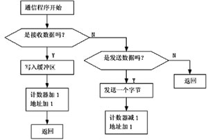
Figure 6 Serial communication block diagram
The field monitor software is written by MCS51 assembly language, which is composed of initialization program and interrupt service program. In the initialization program, the timer T0 is defined as a 6.25ms interrupt, that is, an interrupt service program is executed every 6.25ms, all operations are placed in the interrupt service program, and no actual operation is done after the main program initialization is completed. The interrupt service routine of timer T0 mainly includes the following subroutines: indicator timing subroutine, signal acquisition subroutine, fault judgment subroutine, fault alarm subroutine, control function subroutine, parameter setting subroutine, parameter reading subroutine, Actively monitor subroutines and automatically patrol subroutines.
System reliability design In the actual field environment of power supply operation, there are often various disturbances such as power supply fluctuations, shocks, electromagnetics, etc. In order to ensure that the single-chip program does not appear "dead", when designing the single-chip system, an automatic reset circuit is used The circuit principle is shown in Figure 7. In this circuit, DS1232 is the "watchdog", which can ensure that the CPU (8032) is automatically reset when the program is not running, so that the single chip microcomputer starts running again. S1 in the picture is the manual reset button.
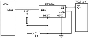
Figure 7 Schematic diagram of automatic reset circuit
In order to test the various functions of the system, the actual environment on site was simulated in the laboratory, and various functions such as centralized monitoring function, parameter setting function, parameter reading function, automatic test function, query statistics function, and distributed notification function were tested. The results Explain that all functions of system design can be realized. In addition, extreme cases have been tested. For example, when 10 on-site monitors simultaneously alarm, the system can ensure that the alarm information is transmitted to the monitoring center in sequence, and the information is not lost; two on-site monitors continuously alarm for more than 12 hours, and the system works normally; When the alarm information database reaches 20,000 alarm messages, the system still works normally, and the query time is within 30 seconds.
Conclusion The system has high reliability, convenience and practicality, and low cost. The comprehensive cost of each monitoring point (machine room) is about 8,000 yuan, while the large-scale monitoring system requires about 100,000 yuan. Big and unrealizable problems.
Pond Uv-C Clarifiers,Pond Uv Sterilizer,Uv Bactericidal Lamp,Uv Sterizilier Lamp
Sensen Group Co., Ltd.  , https://www.sunsunglobal.com