Antennas are an important component in RF systems and have a significant impact on performance. High performance, small size, and low cost are the most common requirements for many RF applications. In order to meet these requirements, it is important to implement an appropriate antenna and describe its performance characteristics. This article describes typical antenna types and explains the important parameters that should be tested when selecting an antenna.
Antenna type When selecting an antenna, the size, cost, and performance of the antenna are the most important considerations. For short-range wireless devices, the three most common antennas are PCB antennas, chip antennas, and whip antennas. The advantages and disadvantages of these three antennas are shown in Table 1.
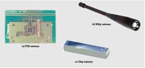
Figure 1 Typical antenna solution
1 PCB antenna design A PCB antenna is not a simple and straightforward thing, because it requires a simulation tool to get a satisfactory solution. In addition to providing an optimal design, configuring such a tool for accurate simulation is also a difficult and time-consuming task.
2 Chip antenna For the antenna, if the board space is very limited, then the chip antenna can be said to be a good solution. This type of antenna can support small solution sizes (even below 1GHz). Compared with PCB antennas, the disadvantage of this antenna is that this solution will increase the cost of materials and placement. The general cost of a chip antenna is between $ 0.10 and $ 1.00. Even though some chip antenna manufacturers claim that this antenna can be matched to a certain 50Ω impedance to suit the frequency band, it usually needs some other matching components.
3 Whip antenna If we focus on performance rather than size and cost, then an external antenna with a connector will be a good solution. These antennas are usually monopole antennas and have an omnidirectional radiation pattern, which means that the performance of the antenna in all directions on a plane is almost the same. The whip antenna should be installed on the ground plane to obtain the best performance. In order to achieve maximum savings, quarter-wavelength lines can provide an efficient solution.
Antenna parameters When choosing an antenna, some of the most important factors to consider include: radiation pattern, antenna efficiency, and antenna bandwidth.
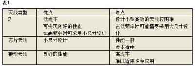
1 Radiation pattern and gain Figure 2 shows how the radiation pattern of the PCB antenna will change in different directions in the PCB plane. When interpreting such a radiation pattern change graph, it is very important to understand several antenna parameters.
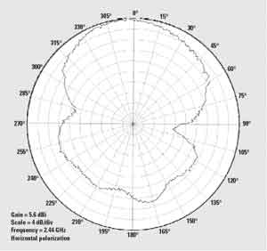
Figure 2 Radiation pattern
In addition to this radiation pattern change diagram, it is also important to relate the radiation pattern to the configuration of the antenna. The radiation pattern is usually tested on three planes at right angles to each other, XY, XZ and YZ. Although it is possible to perform full 3D graphics measurement, it is generally not done because it is a time-consuming task and requires expensive equipment. Another way to define these three planes is to use a spherical coordinate system. These three planes will be defined by θ = 90 °, Φ = 0 ° and Φ = 90 °. Figure 3 shows how to associate the spherical symbol with these three planes. If no information is given on how to relate the radiation direction on the radiation pattern diagram to the antenna configuration, then 0 ° is the X direction and the angle on the XY plane increases toward the Y direction. As far as the XZ plane is concerned, 0 ° is in the Z direction, while the angle increases toward the X direction. For the YZ plane, 0 ° is in the Z direction, and the angle increases toward the Y direction.

Figure 3 Spherical coordinate system
Gain or reference level usually refers to an omnidirectional radiating antenna, which is an ideal antenna with the same radiated power in all directions. When an omnidirectional antenna is used as a reference, the gain is in dBi units, or is specified as the equivalent omnidirectional radiated power (EIRP). The outer circle in Fig. 2 is equivalent to 5.6dBi, and the 4dB / div symbol at the lower left indicates that the emission level has been reduced by 4dB for all gradually increasing small circles. Compared with the omnidirectional antenna, the PCB antenna will have a high level of 5.6dB radiation in the 0 ° direction.
As shown in Equation 1, the antenna gain G is defined as the ratio of the maximum radiation intensity to the average radiation intensity multiplied by the antenna efficiency. 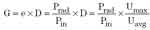 (1)
(1)
Among them, Umax is the maximum radiation intensity, Uavg is the average intensity, the ratio of these two values ​​is called directivity D. The resistance loss of the antenna element and the reflection at the feed point of the antenna together determine the efficiency e, which is the radiated power obtained by dividing Prad by the input power Pin. High gain does not necessarily mean that the antenna has high performance. Generally, mobile systems require an omnidirectional radiation pattern so that their performance will be roughly uniform in all antenna directions. For applications with fixed positions such as receivers and transmitters, higher performance can be obtained when the antenna is pointed in other high-gain radiation directions.
In order to accurately measure the antenna radiation direction, it is very important to measure only the direct wave of the device under test and avoid reflected waves that affect the measurement result. To minimize the pickup of reflected energy, these measurements are usually made in an echo-free room or antenna test field. Another requirement is that the signal measured in the far sound field of the antenna must be a plane wave. As shown in Equation 2, the far sound field distance Rf is determined by the wavelength λ and the maximum antenna size DIM. Due to the limited space in the echoless room, some large, low-frequency antennas are usually tested in outdoor antenna test fields.

(2)
2 Polarization Polarization is a description of the direction of an electric field. All electromagnetic waves propagating in free space have electric and magnetic fields perpendicular to the direction of propagation. In the case of considering polarization, the electric field vector is usually described, and the magnetic field is ignored, because it is orthogonal and proportional to the electric field. For best performance, both the receiving and transmitting antennas should have the same polarization. In fact, most antennas in short-range applications produce polarization in multiple directions. Because indoor equipment is subject to many reflections, polarization is not as important as some outdoor working equipment.
3 Bandwidth and impedance matching The two common methods for determining the antenna bandwidth are: 1) measuring the radiated power while adjusting the carrier in the relevant frequency band; 2) using a network analyzer to measure the reflection at the antenna feed point. Figure 4 shows the first method, which measures the radiated power of a 2.4GHz antenna with an output power variation of close to 2dB in the 2.4GHz band, while also having a maximum radiation close to the center of this band. This measurement method is completed by adjusting the continuous wave signal of 2.3 ~ 2.8GHz. Such methods should be performed in an echoless room to obtain the correct absolute bandwidth level. However, this method is very useful even in the absence of an echoless room.

Figure 4 2.4GHz antenna bandwidth
Measurements in an ordinary laboratory environment can give a relative result, which indicates whether the antenna has the best performance in the ideal frequency band. The performance characteristics of the receiving antenna used to make this measurement will have an impact on the measurement results. Therefore, it is very important that the antenna has approximately the same performance in the measurement band. Such precautions help to ensure that the relative changes in performance observed in the measurement band are effective.
The second method to describe the characteristics of the antenna bandwidth is to measure the reflected power at the feed point of the antenna. Such measurements can be made by disconnecting the antenna and connecting a network analyzer to the antenna using a coaxial cable. The bandwidth of an antenna is usually defined as the frequency range where the reflection is below -10dB, or the VSWR is less than 2. This is equivalent to less than 10% of the effective power being reflected by the antenna in this frequency range.
4 The ideal size, cost and performance of the antenna should not only be very small, zero cost, but also have excellent performance. However, in real life, it is very necessary to seek a compromise between these indicators. When seeking a small antenna solution, a chip antenna is a better alternative. This is especially true at frequencies below 1 GHz, because chip antennas allow the use of smaller solutions than traditional PCB antennas. But the main disadvantages of chip antennas are higher cost and typical narrowband performance.
2.54mm (.100") Pin Headers
Antenk`s line of 2.54mm pitch pin headers are durably made for high vibration environments, for board-to-board or PCB to PCB Connectors, with industry-leading current of 3.0A. Designed for low-profile applications, this pin header is made from high-temperature thermoplastic and is offered with several means of connections and mounting styles such as through-hole (THM) or surface mount (SMT) and can be in vertical (straight), elevated or at a right angle configuration/orientation
Pin header customization is also available upon your request. The 2.54mm pitch pin header is highly recommendable for signal and low power PC board connections when space is at a premium and when 1.0mm and 1.27mm pitch headers cannot dissipate the required current. In addition, the 2.54mm pitch pin header holds an excellent mating quality that fits with various types of female connectors.
Applications of 2.54mm Pitch Pin Headers
Motherboard Connectors
The Motherboard of a computer holds together many of the crucial components such as the central processing unit (CPU), memory and connectors for input and output devices.
Printer Connectors
Automotive PC Connectors
Smart, high power automotive PC power supply garners its capabilities from quality pin headers, designed for general purpose battery powered applications. These are manufactured to provide power and to control the motherboards' switch based on ignition status.
Battery Connections
Rechargeable battery packs, battery balancers, battery eliminator circuits. Battery connections rely on the ability of the current to pass reliable and solid current. This prevents overheating in the circuit and voltage drop.
Medical Diagnostic and Monitoring equipment
Communications: Telecoms and Datacoms
Industrial and Automotive Control and Test
Mount Type: Through-hole vs Surface Mount
2.54mm pitch pin (male) headers are offered in either Surface-mount or Through-hole mount termination. At one side of this pin header is a series of pins which can either be mounted and soldered directly onto the surface of the PCB (SMT) or placed into drilled holes on the PCB (THM).
Through-Hole (Poke-In)
Best used for high-reliability products that require stronger connections between layers.
Aerospace and military products are most likely to require this type of mounting as these products experience extreme accelerations, collisions, or high temperatures.
Useful in test and prototyping applications that sometimes require manual adjustments and replacements.
2.54mm vertical single row header, 2.54mm vertical dual row header, 2.54mm Elevated single row pin header, 2.54mm Elevated dual row pin Header, 2.54mm Right-angle single row header and 2.54mm Right-angle dual row header are some examples of Antenk products with through-hole mount type.
Surface-Mount
The most common electronic hardware requirements are SMT.
Essential in PCB design and manufacturing, having improved the quality and performance of PCBs overall.
Cost of processing and handling is reduced.
SMT components can be mounted on both side of the board.
Ability to fit a high number of small components on a PCB has allowed for much denser, higher performing, and smaller PCBs.
2.54mm Right-angle Dual Row pin header, 2.54mm SMT Single row pin header, 2.54mm SMT Dual row pin header and 2.54mm Elevated Dual Row Pin Header are Antenk`s SMT pin headers.
Soldering Temperature for 2.54mm Pitch Pin Headers
Soldering SMT pin connectors can be done at a maximum peak temperature of 260°C for maximum 60 seconds.
Pin-Type: Vertical (Straight) and Right-Angle
2.54mm pitch headers may be further classified into pin orientation as well, such as vertical or straight male header or right-angle male header.
One side of the series of pins is connected to PCB board in which the pins can be at a right-angle to the PCB surface (usually called "straight" or [vertical") or.
Right-Angle Pin (Male) Header Orientation
Parallel to the board's surface (referred to as "right-angle" pins).
Each of these pin-types have different applications that fit with their specific configuration.
PCB Connector Stacking
Elevated Pin Header Orientation
Elevated pins aka Stacked Pins or Mezzanine are simply stacked pin headers providing an exact distance requirement between PCBs that optimizes electrical reliability and performance between PCB boards.
This type of configuration is the most common way of connecting board-to-board by a connector. First, the stacking height is calculated from one board to another and measured from the printed circuit board face to its highest insulator point above the PCB.
Single, Dual or Multiple Number of Rows
For a 1.0mm straight or vertical male pin header, the standard number of rows that Antenk offers ranges from 1 to 2 rows. However, customization can be available if 3, 4 or n number of rows is needed by the customer. Also, the number of contacts for the single row is about 2-40 pins while for dual row, the number contacts may vary from 2-80 pins.
Pin Material
The pins of the connector have been designed with copper alloy. With customer`s demand the pins can be made gold plated.
Breakaway design
The pin headers are also equipped with a breakaway design making them fully compatible with their female receptacles.
Custom 2.54mm Pitch Pin Headers
Customizable 2.54 mm pitch pin headers are also available, making your manufacturing process way faster as the pins are already inserted in the headers, insulator height is made at the right size and the accurate pin length you require is followed.
Parts are made using semi-automated manufacturing processes that ensure both precision and delicacy in handling the headers before packaging on tape and reel.
Tape and Reel Packaging for SMT Components
Antenk's SMT headers are offered with customizable mating pin lengths, in which each series has multiple number of of circuits, summing up to a thousand individual part number combinations per connector series.
The tape and reel carrier strip ensures that the headers are packaged within accurately sized cavities for its height, width and depth, securing the headers from the environment and maintaining consistent position during transportation.
Antenk also offer a range of custom Tape and reel carrier strip packaging cavities.
Male Header,2.54Mm Male Header,2.54Mm Male Header Pins,2.54Mm Pin Header,0.100in Male Header,0.100in Pin Header Connector
ShenZhen Antenk Electronics Co,Ltd , https://www.antenkelec.com