During the construction and maintenance of the electromechanical equipment installation project, cable failures caused by various reasons will be faced. Therefore, it is necessary to have applicable theories and methods to solve various types of faults. This paper describes the traditional methods of detection.
For the fault point detection of the cable, it is generally necessary to go through the three main steps of fault type diagnosis, fault point ranging, and precise determination. Fault type diagnosis is mainly to determine the fault phase of the cable fault point, which is high-resistance grounding or low-resistance grounding, so that the tester can select the appropriate detection method. The fault point ranging is also called pre-positioning. The test cable is applied on the fault cable core line or online to measure and analyze the fault information. The fault distance is initially determined, and the fault range is minimized to facilitate the precise determination of the point.
Pre-positioning methods can generally be summarized into two categories, namely classical methods, such as bridge methods; modern methods, such as low-voltage pulse method, high-voltage flashover method. The precise determination point is based on the predetermined distance, and the actual position of the fault point is accurately determined. The precise point method mainly includes acoustic measuring point method, induction fixed point method, time difference fixed point method and synchronous fixed point method.
Traditional detection method for cable failureCable laying is the sub-item construction with the highest economic value in electromechanical installation and construction. It is also an important facility to ensure the normal operation of equipment. In the actual construction and maintenance operation, the design is often unreasonable due to the laying method, the construction personnel are not properly operated, and the pests are small. The effects of various factors such as the destruction of animals cause damage to the cable and cause malfunction. In a large number of engineering practices, we found that the cable fault is a high-resistance current leakage fault (resistance value is greater than or equal to 1 Ω), which is often caused by the destruction of the insulation layer. Low-resistance faults are generally caused by phase-to-phase or short-circuit to ground, which is caused by insufficient insulation means during construction. However, the probability of occurrence is small, mainly due to prevention, and quality is strictly controlled during the construction phase. Reduce the occurrence of accidents.
Cable faults may occur at any stage of construction, commissioning, maintenance, etc. of the distribution line. Except for a small number of cable faults that occur during the construction and commissioning phases, more cable faults occur during maintenance operations. The aging of the wiring system gradually appears, causing the device to frequently trip to the user. Therefore, the user must be proficient in the cable detection method.
In the process of cable fault detection, it is divided into high voltage detection or low voltage detection by means of high voltage or low voltage. High voltage detection is used for cable faults in various situations such as low resistance, open circuit and high resistance. The low voltage detection method is only suitable for low resistance. Open circuit conditions, so high-voltage detection methods are often used in actual testing.
Common detection methods for cable faultsThe bridge method, the bridge method is a relatively traditional circuit fault detection method and the effect is better. The advantages are simplicity, convenience and high precision. The disadvantage is that it is not suitable for detecting high resistance and flashover faults. Because the fault resistance is very high, the current of the bridge is very small, and the instrument with general sensitivity is difficult to detect.
In addition, when detecting by the bridge method, it is necessary to know the original data such as the exact length of the cable. When the cable line is composed of cables of different cross-sections, conversion is also required, and the bridge method cannot measure three-phase short-circuit or open-circuit fault. However, it also has certain drawbacks. Because the voltage of the bridge and the sensitivity of the galvanometer are relatively poor, it is only suitable for cable faults with DC resistance below 100K and relatively low resistance. This method cannot be used for high-resistance equipment, open-circuit fault current leakage, etc.
Low-voltage pulse detection method, when using the low-voltage pulse reflection cable fault detection method, the low-voltage pulse should be injected into the damage line in the specific operation. When the pulse is transmitted along the cable line to the fault point, that is, the impedance encountered during the current transportation is not met, the reflected pulse is displayed on the detecting device, and the data record is reflected by the device, and the time difference between the transmitting and reflecting pulses is calculated. And its wave velocity calculation in the cable to get the actual distance of the fault point from the test point. This method is relatively simple, and the test results are intuitive and significant, and can be directly detected without determining the fault data. However, it also has the drawback that it must understand the cable setting trend, and it cannot be applied to high impedance and flashover cable failure.
Pulse voltage method and pulse current method, pulse voltage method includes DC high voltage flashover method, and impact high voltage flashover method. The basic principle of the pulse voltage method is to use the direct current (or shock) high voltage signal to break through the fault point of the cable, record the round trip time between the test point and the fault point of the discharge voltage pulse, and calculate the position of the fault point accordingly. The advantage of the pulse voltage method is that the test speed is faster because it is a transient pulse signal generated directly by the breakdown of the fault. The disadvantage is that in the fault discharge, especially in the impact flashover test, the voltage pulse signal is measured by the capacitor (resistor) voltage divider, and the voltage waveform coupled by the voltage divider is difficult to distinguish. The basic principle of the pulse current method is to click through the fault of the cable, measure the current traveling wave signal generated during the breakdown, and calculate the position of the fault point according to the round trip time between the test point and the fault point of the current traveling wave.
The limitation of the pulse current method is that it uses a transformer to couple the pulse current. The waveform is more complicated. Due to the attenuation of the traveling wave signal caused by the loss of the core dielectric and the reflection and other interference factors of the intermediate joint, the fault waveform is often in error. Very big.
Cable short-circuit quick checkIf there is a cable short circuit, the mechanical multimeter can be used to determine the resistance value of the two short sections of the cable. The end of the resistance is the head end A, the resistance is RA; the other end is B, the resistance is RB; the total cable length is L, the distance from the short-circuit point to the head end is LA, and the distance from the short-circuit point to the tail end is LB. inferred:
(RA+RB)/RB=(LA+LB)/LB, which can be derived from the above formula LB=( LA+LB)*RB/(RA+RB) (1)
Example: The cable of the power distribution room to the pump room of a factory has been checked for short circuit fault. This cable is about 400m long. The resistance of the two sections of the multimeter is 100Ω and 4Ω.
Bringing the two resistance values ​​into (1) gives: LB=400&TImes; 4/(10+4) =1 600/14≈114m.
This method only uses the low-resistance faulty cable, the advantage is that it does not depend on equipment and experience, and ordinary electricians can master it. During the construction of the lighting project of Liangshan Tunnel in Yuhuai Railway Park, our unit is responsible for the construction and maintenance of the lighting project of the Liangliangshan Tunnel and the Pingdao. Due to the high humidity in the air at the construction site, the insulation effect of the cable joints is affected. The impact, short-circuit trip failure occurred in many places after long-term use. Due to the running railway tunnel or the horizontal guide immersed in the water, the working site can be up to 11 kilometers in length. It is impossible to use the vehicle equipment during maintenance. It can only rely on the walking method to enter the fault location. The load capacity is limited, so the cable short circuit quick check method It is the ideal detection method.
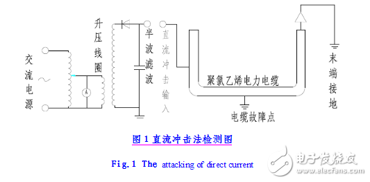
DC shock method (impact flashover method)The DC impulse method uses the DC voltage to generate a pulse voltage through the ball gap discharge, which generates multi-spectral discharge current and sound, light and magnetic field at the insulation damage of the sheath, and the accurate location of the fault point can be obtained by detecting the discharge signal in the field. The discharge intensity depends on the amount of charge stored in the filter capacitor, and the amount of charge stored is proportional to the DC voltage and capacitance, ie Q = CU. The test device has simple structure and simple operation. The detection diagram is shown in Figure 5. It is mainly suitable for newly laid cables. It is especially suitable for cables that have not been landfilled. The sound of discharge at the fault point can be heard with bare ears, and the effect is obvious at night. For the buried cable, the sound magnetic method or the acousto-magnetic asynchronous tester should be equipped for measurement and positioning. In any case, an audio amplifier is provided and the discharge sound is monitored with headphones.
During the electromechanical installation of Guangzhou Xinguang Tunnel, the electrician found that the pump often tripped during the commissioning of the project. However, the multimeter was used to detect that the cable did not have a low resistance fault. The cable resistance and insulation resistance were in the normal range. In this case, The simple self-made filter capacitor device continuously supplies power to the faulty cable. The electrician listens to the discharge sound along the line at the landfill position, and finally hears the obvious pulse sound at 40 meters outside the transformer room, and marks the range. Then, the fault location was excavated, and the cable was found to have obvious damage to the cable skin, and no fault occurred after the repair.
The advantage of this method is that the method of use is simple, and it can be mastered by simple electricians by simple training. It is the first choice in the cable short-circuit quick check method.
The step voltage method is currently the most widely used and effective high-precision positioning method for judging the fault point of a buried cable. The equipment used in the test is mainly a high-voltage series wave pulse generator and a set of potentiometers or millivoltmeters with probes.
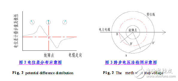
Among them, the series wave pulse generator can be modified by the DC impact method power supply. There are two detection methods: one is to use the feature that the step voltage directly above the fault point is zero, and the polarity of the step voltage on the two sides of the fault point is opposite and the maximum value is reached, and the fault point is located. Schematic diagram of the potential difference distribution of the differential meter along the cable; the second is to use the discharge current to circulate above the fault point, and find two equipotential points in different directions. The fault point must be located in the vertical of the two groups of equipotential points. At the intersection of the bisectors, AA' and BB' in Fig. 3 are two sets of equipotential lines, respectively.
This method is mainly for judging the fault of the buried cable, and can effectively and accurately locate the fault. Method 1 is easier to master. During the engineering maintenance process of the Keshan Civil Air Defense Project in Guangzhou, the buried cable has a high-resistance leakage fault. The engineering and technical personnel used this method to open the ground and found that the mouse skin was damaged due to the outer skin.
MPO/MTP Cassette Module possess optical fiber branching patch cords inside to split the 12-core MPO / MTP connector into simplex or duplex LC connector.
Simplex or duplex connectors are placed in front of the modules, and one or two MPO/ MTP connectors are placed at the back of the modules.
The branching patch cord connect the front LC and the near MPO/MTP connectors. This type of modules can be easily installed in 1U and 4U Chassis.Mpo Cassette Module,Cassette Module For 1U Patch Panel,Mpo-Lc Cassette Module,Mpo Cassette Moudle 24F
ShenZhen JunJin Technology Co.,Ltd , https://www.jjtcl.com