The following figure is the main slave sr flip-flop circuit diagram
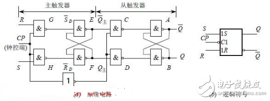
Figure 1 from the sr flip-flop circuit diagram
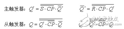
CP=1: CP/=0, G3, G4 are blocked, the output is 1, and the output from the trigger remains unchanged.
G8, G9 open in the main trigger, output 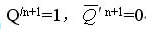
CP: 1 → 0: G7, G8 are blocked, the output is 1, the main trigger output remains in the original state. 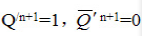
The slave trigger outputs Q=1 according to the main trigger.  =0, the trigger is 1 state
CP=0: The main trigger remains and the slave flip-flop remains.
CP: 0 → 1: The slave is blocked and the output is held.
(2) S=0, R=1When CP=1: CP/=0, G3, G4 are blocked, the output is 1, and the output from the trigger remains unchanged.
In the main trigger, G8 and G9 are turned on, and the output is: 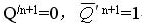
CP: 1 → 0: G7, G8 are blocked, the main trigger output remains in the original state 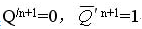
The slave trigger outputs Q=0 according to the main trigger.  =1, the trigger is 0 state
CP=0: The main trigger remains and the slave flip-flop remains.
CP: 0 → 1: The slave is blocked and the output is held.
(3) S=R=0: the main trigger remains in the same state.CP: 1 → 0, the slave flip-flop remains unchanged.
(4)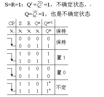
Constraint: SR=0
In summary, the operation of the master-slave flip-flop shown in Fig. 1(a) is performed in two steps. In the first step, when the CP transitions from 0 to 1 and CP=1, the main trigger receives the input signal excitation, and the state changes;  Change from 1 to 0,
  =0, the slave trigger is blocked, so the trigger state remains unchanged. This step is called the preparation phase. The second step is when the CP changes from 1 to 0, and during CP=0, the main flip-flop is blocked, the state remains unchanged; and the slave trigger clock
  The transition from 0 to 1 receives the state of the main flip-flop at this moment, and the trigger output state changes.
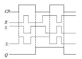
Figure 2 Working waveform from sr flip-flop
During a change cycle of the CP, only at the moment when the falling edge of the CP comes, the trigger output state (Q,  In order to have a flip, this triggering method is called pulse triggering. Therefore, such a trigger can effectively overcome the flip. Figure 2 shows the operating waveform of the master-slave RS flip-flop. In Figure 1(b), the small circle "〇" at the CP end indicates that the flip-flop is triggered by the falling edge of the CP.
Silicone Protective Sleeve,Silicone Sleeve For Glass Bottle,Silicone Water Bottle Sleeve,Bottle Silicone Sleeve
Nantong Boxin Electronic Technology Co., Ltd. , https://www.ntbosen.com