ESP is the commanding height of the technology in the field of active safety of automobiles. This technology is monopolized by large foreign companies, and the country is still in the research and development stage. In the ESP development process, a large number of real vehicle tests are required. There are two major difficulties in this test: one is that the test is quite dangerous, and the other is that the test is very demanding on the site. Therefore, the development of hardware-in-the-loop simulation platforms has become an urgent need. This simulation platform plays an important role in accelerating the algorithm development of ESP controllers. This article uses NI PXI as a lower computer to build the system.
This article refers to the address: http://
Background of the project
After in-depth research, this program mainly considers performance, price, and ease of implementation, and finally chose NI PXI and cRIO solutions for system construction. The main research is XPC mode, PXI system and dSpace system. The XPC method is cheaper, but it is not convenient to use. The price of the dSpace system is much higher than that of the PXI system. However, the performance difference between the two is not very large.
System architecture
The ESP hardware-in-the-loop simulation platform consists of five parts: the upper computer, the lower computer, the controller, the actuator, and the sensor.
The host computer is used to monitor the simulation process, analyze and save the simulation results. The lower-end machine runs the vehicle model, and currently adopts a 15-DOF vehicle model, which can well simulate the response of the vehicle under braking, driving, high-speed steering and combined conditions. The controller runs a control algorithm to control the motion of the vehicle. Actuators are hydraulic control units, brake lines and brakes. The sensor is a pressure sensor that takes the pressure values ​​of the various wheel cylinders and the master cylinder and transmits the pressure signal to the controller and the lower position machine to form a closed loop system. The structure of the simulation platform is shown in Figure 1.
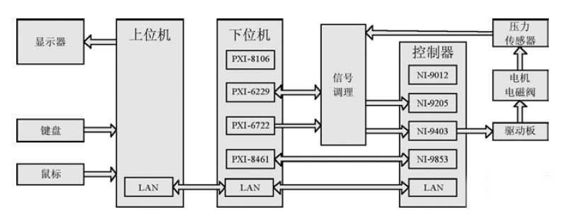
Figure 1 Simulation platform structure
Simulation platform structure
In Figure 1, the upper computer, the lower computer and the controller are connected by a network cable, and the monitoring of the simulation process by the upper computer is realized by sharing variables.
System hardware design
Run the vehicle model with PXI to simulate the vehicle's motion response and provide signals to the controller. In the actual vehicle test, the signals obtained by the controller include the brake signal, the master cylinder pressure signal, the four wheel speed signals, the steering wheel angle signal, and the lateral acceleration signal and the yaw rate signal. In addition, the controller also needs to communicate with the engine control system via CAN to control the output torque of the engine. PXI should be able to perform the above functions and collect pressure sensor signals to calculate the vehicle's motion state.
PXI collects the pressure signals of the master cylinder and each wheel cylinder through the analog input function of the M series data acquisition card PXI-6229, and collects the brake signal with the digital input function of PXI-6229. The PXI-6722's analog output function output voltage is used to indicate steering wheel angle, lateral acceleration, and yaw rate. At the same time, PXI-6722 outputs 4 analog voltages, and converts the voltage into corresponding frequency signals through the voltage-frequency conversion module to simulate four wheel speed signals. In addition, CAN communication on the real car is realized by PXI-8461 and NI9853.
On the controller side, when using cRIO for rapid prototyping, the analog voltage is acquired by the NI-9205 to obtain the values ​​of the individual sensors. The NI-9403's input function is used to acquire the brake signal and the wheel speed signal, and the NI-9403's digital output function controls the motor and solenoid action.
In terms of actuators, the hydraulic control unit uses Bosch's ESP 8.0 hydraulic control unit. The brake system uses the brake lines and brakes of the Gold Cup passenger car. The simulation platform was built on the Jinbei passenger car. We modified the brake pipe of the Jinbei passenger car and installed the pressure sensor and HCU (complete vehicle controller).
System software design
In software, the start and end of the simulation test are controlled by sharing variables, and the data in the lower computer is recorded by global variables, and then uploaded to the upper computer through the network. These three parts of the program use state machine mode to facilitate software upgrades and maintenance. The overall software structure is shown in Figure 2.
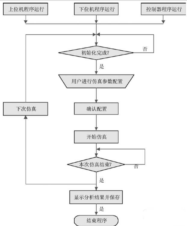
Figure 2 system software block diagram
Host computer monitoring software
The host computer monitoring software is mainly divided into two parts: the simulation process monitoring and viewing the simulation data. The simulation process monitoring includes parameters calling, simulation control, real-time parameter monitoring, driver input during simulation, etc., and can simulate the simulation mode, shift strategy, simulation time, etc., and realize the simulation of various situations conveniently and flexibly.
Looking at the simulation data section, you can observe the comparison simulation data, vehicle motion playback, data saving and recall during the simulation. The simulation process control interface is shown in Figure 3.
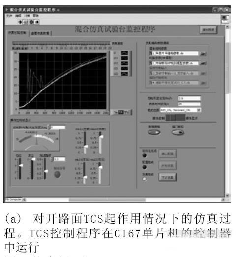
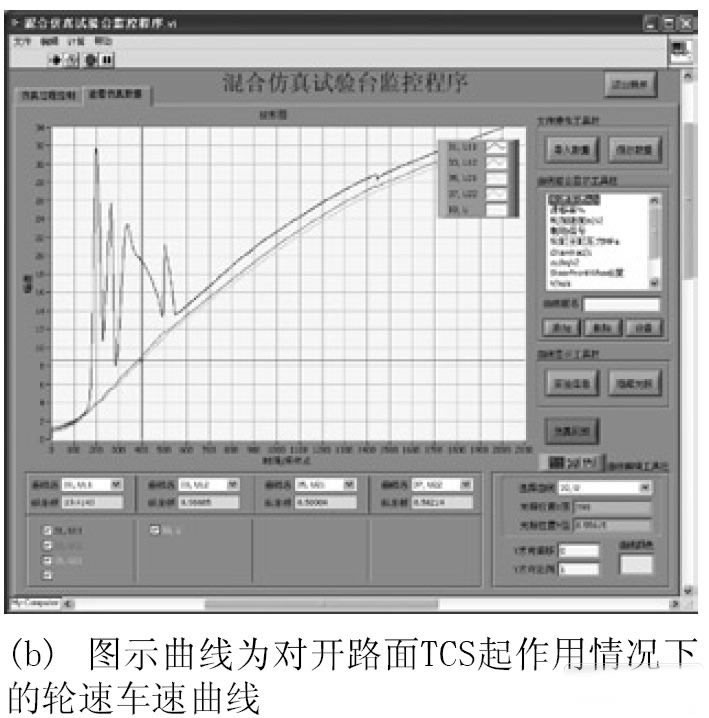
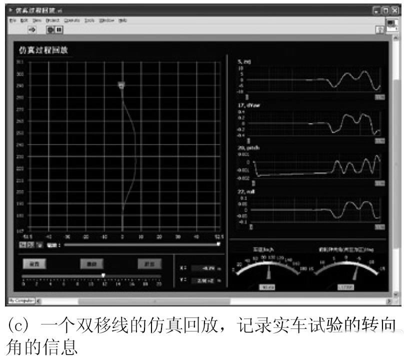
Figure 3 simulation interface
Among them, in Fig. 3(b), the curve of 70 parameters in the simulation process can be observed. The simulation data can be saved and recalled, and the vehicle trajectory can be graphically displayed by clicking the “Emulation Playback†button at the bottom right. In Fig. 3(c), the recorded steering angle information can be input to the system at the actual time interval during the simulation, and the simulation can obtain the response of the vehicle.
Lower computer simulation software
The lower machine runs the whole vehicle model and adopts a 15-DOF vehicle model. The 15 degrees of freedom are: 6 degrees of freedom of the vehicle's longitudinal, lateral, vertical translation and rotation, 8 degrees of freedom of rotation and vertical translation of the four wheels, and 1 degree of freedom of the steering system.
In the simulation process, the lower machine collects the pressure signals of the master cylinder and the four wheel cylinders through the data acquisition card in a cycle of 1 ms, thereby calculating the force of the vehicle and obtaining the motion state of the vehicle. The status parameters are output to the controller via the data acquisition card. At the same time, the lower computer saves the data of the vehicle motion state in the memory of the lower computer with a period of 10ms, and uploads it to the upper computer after the simulation ends. And the lower computer continuously detects the control signals sent by the upper computer, such as the steering signal, the shift signal, the throttle signal, etc., in a cycle of 10 ms. The implementation of this parallel structure makes complex functions easy to implement.
Controller software
The ESP control algorithm is running on the controller. The controller determines whether the vehicle state is a dangerous condition by receiving signals of various sensors. If a danger is detected, a control command is output to the actuator, and the brake system is actively interfered by the action of the motor and the solenoid valve. The CAN communication is sent to the engine management system to control the vehicle drive, thereby relieving the crisis. Considering the compatibility of the test bench, the controller part can use NI cRIO as the controller, and adopt the first generation ESP controller (the main control chip is C167), or the second generation ESP controller (the main control chip is XC164). .
Simulation results
Comparing the simulation results with the actual vehicle test results, the degree of agreement between the two is very good, indicating that the hardware-in-the-loop simulation platform can effectively simulate the vehicle motion state. The construction of the simulation platform can accelerate the development of ESP control algorithms.
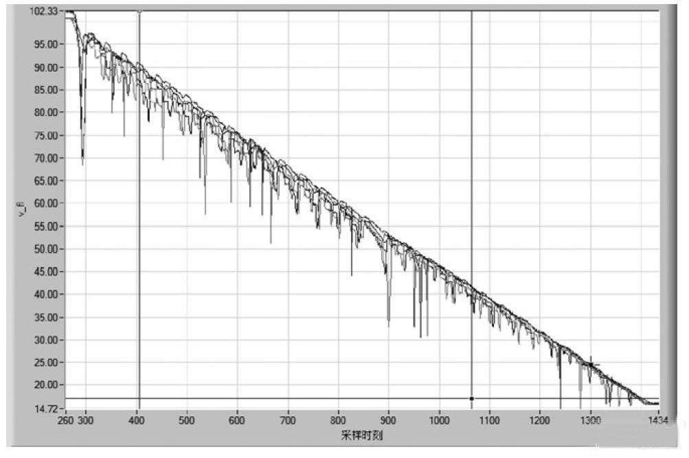
Figure 4 shows a set of wheel speed data for testing ABS function under certain parameters, which is very similar to the actual vehicle test results, indicating that the simulation platform has high precision.
Figure 4 A set of wheel speed data for testing AVS function under certain parameters
in conclusion
This paper builds an ESP hardware-in-the-loop simulation platform based on PXI and cRIO. The platform can place the controller in the simulation loop to facilitate testing of the algorithms in the controller. The construction of the simulation test bench improves the development speed of the ESP control algorithm.
PZT Piezoelectric Cylinders/Tubes
Yuhai company develop and produce of various tube/cylinder sizes, bearing variety of electrode and metallisation configurations. The tubes is fabricated from various published and additional custom in-house Piezoelectric Material formulations for applications such as high power, sensitivity, stability needs.
Features
- · Choice of metallisation (Silver, Nickel, Gold and others on request)
- · Evaporated and chemically deposited metallisation's available
- · Thickness/Radial frequency tuning available on request
- · Wrap around electrode configuration
- · Wide choice of PZT formulations
aApplications include
- · Hydrophones
- · Fibre optic stretcher
- · Augmented reality
- · Torpedo decoys
- · Accelerometers
- · Pressure sensors
- · Print head transducers
- · Oil and gas exploration
- · Scientific equipment
Tubes
Height:
1-100mm
OD:
6-180mm
ID:
5-150mm
Wall: 0.5-15mm
Piezo Tube,Piezoelectric Tube,Piezo Electric Tube,Piezo Ceramic Tubes
Zibo Yuhai Electronic Ceramic Co., Ltd. , https://www.yhpiezo.com