introduction
With the rapid development of computer, communication and network technologies, low-voltage high-current DC/DC converters have become an important research topic. In the traditional diode or Schottky diode rectification method, the rectification loss is the main loss of the converter due to the large forward voltage drop. The power MOSFET has low on-resistance, short switching time, and high input impedance, making it a preferred rectifier for low-voltage, high-current power converters.
1 synchronous rectifier forward converter
Figure 1 shows a voltage self-driven synchronous rectification forward converter. In Figure 1, two separate auxiliary windings N4 and N5 coupled to a transformer are used to drive two synchronous rectifiers S201 and S202, respectively. When the main switch turns on, the secondary winding of the transformer is negatively connected. The gate voltage of S201 is high, and the conduction is rectified. When the main switch is turned off, the secondary winding is positively negative, and the gate of freewheeling S202 is high. Freewheeling.
In the forward converter, synchronous rectification S201. The operation of the transformer is related to the magnetic reset method of the transformer. If the auxiliary winding reset circuit shown in FIG. 1 is used, the output current flows through the freewheeling synchronous rectifier S202 after the reset ending process, and the voltage at the time the transformer voltage remains zero is zero, but the gate of S202 has no driving voltage.
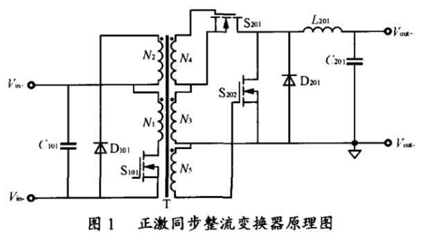
The output current must flow through the body diode of the S202. The MOSFET body diode has a high forward voltage, a poor reverse recovery characteristic, and a very large conduction loss, which greatly reduces the advantages of using MOSFET rectification. In order to solve this problem, the simpler method is the drain of the S202 and A Schottky diode D201 is connected in parallel between the sources. In the period of S202 turning off, instead of the freewheeling of the body diode of S202, this method has few added elements, and the circuit is simple and practical.
In order to optimize the driving waveform, separate auxiliary windings can be used to drive the two synchronous rectifiers respectively. Compared with the conventional synchronous rectifiers directly driven by the secondary windings, this driving method has no operating current through the driving windings, and therefore does not The time required to establish the output current is such that the MOSFET can be turned on quickly, and the dead-time at turn-on, that is, the turn-on time of the body diode is reduced by half. On the other hand, the driving voltage is not limited to the secondary voltage, and the appropriate driving voltage can be obtained by adjusting the auxiliary coil.
Synchronous rectification under light load conditions
For a forward converter, the output current is maintained by the energy in the output energy storage inductor during the time when the main switch is off. Therefore, the converter has two possible operating conditions: continuous current mode of the inductor (CCM, continuous current mode). ) Discontinuous current mode (DCM).
2. 1 Inductor Current Continuous Mode CCM
When the load current is large, the inductor current will not fall to zero during the entire cycle. Each switching cycle can be divided into two phases. In the t1 phase, S201 is turned on, S202 is cut off, and the voltage across the inductor is Vs-Vo. (where, Vs is the secondary winding voltage of the transformer, Vo is the inverter output voltage), and the inductor current continues to rise; in the t2 phase, S201 is turned off, S202 is turned on, the voltage across the inductor is -Vo, and the inductor voltage continues to drop. In a steady state, the average charging current and the discharging current of the filter capacitor C are equal in one switching cycle. Therefore, the average value Io of the load current output by the converter is the average value of iL. Since the load current is large, the inductor current iL is in the entire cycle. None will fall to zero and the inductor current direction will not change, as shown in Figure 2(a).
When the load current Io decreases, both ILmax and ILmin decrease, and when the load current Io decreases so that ILmin is exactly zero at the end of Toff, 2(b), the load current at this time is called the critical current.
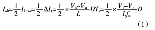
When the load current is further reduced, for the forward converter with secondary diode freewheeling at the secondary side, there will be intermittent inductor current operation, as shown in Figure 2(C).
When the secondary side uses synchronous rectification, due to the bidirectional conduction characteristics of the freewheeling MOSFET, the inductor current at this time can be reversed, as shown in Figure 2(d), generating a circulating current. With circulation, it will consume circulation energy. The magnitude of this energy is related to the output filter inductance. The smaller the output filter inductance is, the larger the circulation current is. The larger the circulating current energy, the greater the loss. Therefore, since the synchronous rectifier cannot automatically switch from the CCM mode to the DCM mode, a large circulating current loss occurs at light load. Recirculation losses, switching drive losses, and switching losses make the converter less efficient at light loads.
In order to avoid reverse loop current formation when the inductor current is lightly loaded, a driving circuit as shown in FIG. 3 can be used. S201 and S202 are two synchronous rectifiers, and Vdd is a reference voltage. After R211 and R212 are divided, a voltage setpoint is added to the comparator's non-inverting input terminal, and the comparator's reverse input terminal is connected to the output terminal. Current sampling resistor R210. When the output current is higher than the critical output current, the comparator outputs a high level. During the off-time of the main switch, S202 and S203 are turned on. The high potential is added to the gate of the freewheeling MOSFET S202, and the S202 is turned on. When the output current is lower than At the critical current, the comparator outputs a low potential, S204, S203, and S202 are all turned off. At this time, the freewheeling operation is completed by the Schottky tube D201 connected in parallel with the S202. The unidirectional conductivity of the Schottky avoids the ring. The formation of road currents.

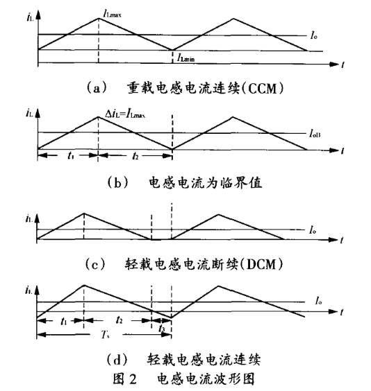
It is worth noting that the freewheeling MOSFET must be turned off before the reverse current is generated. If the MOSFET is turned off after the reverse current has been generated, the reverse current rapidly drops, resulting in a large di/dt and a very high voltage spike across the source and drain of the freewheeling MOSFET. The spike may even be higher than the withstand voltage of the MOSFET, causing the freewheeling MOSFET to breakdown, as shown in the test waveform in Figure 4.
In this control mode, the freewheeling synchronous rectifier is freewheeling during heavy load, and the freewheeling current flows from the Schottky tube during light load. The inductor current will enter the DCM mode, which reduces the conduction loss and improves the light load conversion. Efficiency.
2. 2 Inductor Current Shutdown Mode (DCM)
In this case, each cycle can be divided into three phases. The t1 and t2 phases are the same as the above-mentioned CCM. If the voltage and the inductor current at both ends of the inductor are exactly zero when entering t3, the circuit is just in a steady state and there will be no oscillation. However, in the actual circuit, it is difficult to guarantee the satisfaction of these two conditions.
In the t3 phase, both S201 and S202 are in the off state. The parasitic capacitance Cp of the inductor L201, the load capacitance C201 and the load form an LC resonant circuit in parallel. Considering C201 1 >>Cp, the oscillation frequency can be obtained as
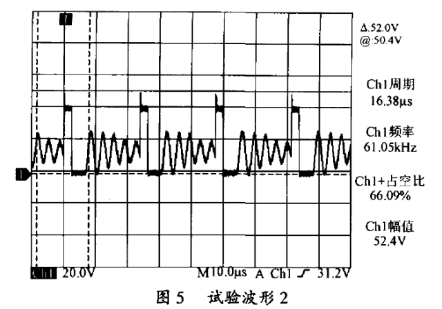
This frequency is often high and will cause significant oscillations across the source and drain of S202, known as the ringing phenomenon. This process is usually under-damped, as shown in the experimental waveform in Figure 5.
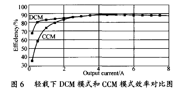
Since the DCM mode can avoid the generation of loop current at light load, it can greatly improve the efficiency of the light load converter. The efficiency comparison of the two circuit modes is shown in Figure 6.
Under light load conditions, the off-going free-wheeling MOSFET is used so that the forward side of the forward converter works in the DCM mode, which can significantly improve the efficiency of the synchronous rectifier converter at light load. Experiments show that the use of the circuit shown in Figure 3 to complete the conversion of secondary current CCM to DCM at light load is a feasible method to improve the light load efficiency of the forward converter.
Disposable electronic cigarettes
vape e cigarette device,vape disposable puff bar,vape disposable,smoke vape pen,smoke pen vape
Shenzhen Aierbaita Technology Co., Ltd. , https://www.aierbaitavape.com